
Efficient crystalline silicon solar photovoltaic power generation sunlight shed

A solar photovoltaic and crystalline silicon technology, applied in photovoltaic power generation, photovoltaic modules, photovoltaic module support structures, etc., can solve the problems of high noise, easy water leakage, easy coverage, etc., and achieve the effect of reducing noise

Active Publication Date: 2021-01-19
清远市德晟嘉恒能源环保工程有限责任公司
View PDF10 Cites 2 Cited by
  • Summary
  • Abstract
  • Description
  • Claims
  • Application Information

AI Technical Summary

Problems solved by technology

[0002] In rural areas, the top of some flat houses is prone to water leakage, and the roof is exposed to the sun and the indoor temperature is extremely high. Therefore, more and more people choose to install sun sheds on the roof. With sun sheds, it can not only shelter from wind and rain, but also increase the living space of the house. The high-efficiency crystalline silicon solar photovoltaic power generation sun shed adopts photovoltaic power generation technology on this basis to meet the above needs and at the same time it can also generate solar power, which not only guarantees people's electricity demand, but also sells the excess electricity to the power supply station. , improve the income of the people, but there are also some defects in the existing sun sheds. Birds are easy to inhabit on the roof of the shed, and the droppings of birds are easy to cover the sun shed to affect the light source acquisition. loud noise

Method used


Image

  • Efficient crystalline silicon solar photovoltaic power generation sunlight shed
  • Efficient crystalline silicon solar photovoltaic power generation sunlight shed
  • Efficient crystalline silicon solar photovoltaic power generation sunlight shed

Examples


Embodiment Construction

[0031] The following will clearly and completely describe the technical solutions in the embodiments of the present invention with reference to the accompanying drawings in the embodiments of the present invention. Obviously, the described embodiments are only some, not all, embodiments of the present invention. Based on the embodiments of the present invention, all other embodiments obtained by persons of ordinary skill in the art without making creative efforts belong to the protection scope of the present invention.

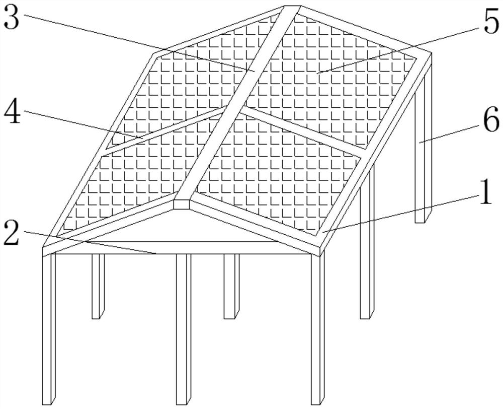
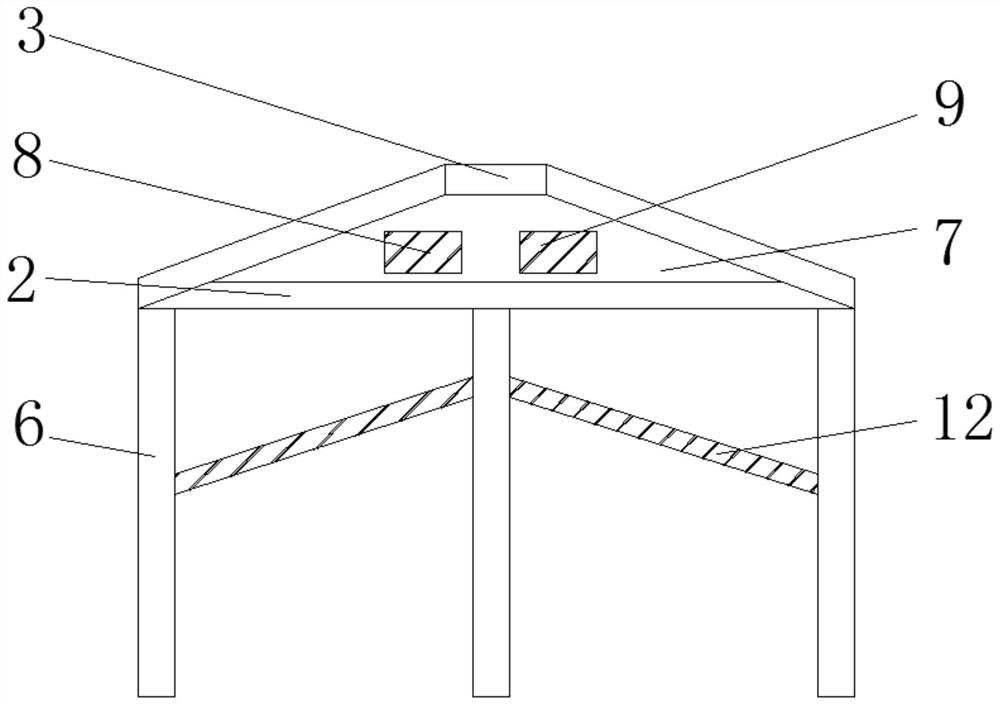
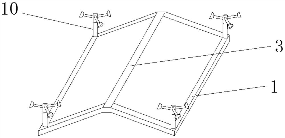
[0032] see Figure 1 to Figure 7 , the present invention provides a technical solution: a high-efficiency crystalline silicon solar photovoltaic power generation sun shed, such as Figure 1 to Figure 2 As shown, including a frame 1, a crossbeam 2 is fixedly installed at the front and rear ends of the frame 1, a central beam 3 is arranged in the upper middle position of the crossbeam 2, and a Slanted beams 4, double-sided power generation solar panels 5 are mo...


PUM

PropertyMeasurementUnit
Widthaaaaaaaaaa

Abstract

The invention discloses an efficient crystalline silicon solar photovoltaic power generation sunlight shed. The sunlight shed comprises frameworks; cross beams are fixedly installed at the front end and the rear end between the frameworks; center beams are arranged in the middles of the upper parts of the cross beams; oblique beams are fixedly installed between the center beams and the frameworks;double-sided power generation solar panels are movably installed between adjacent oblique beams; supporting columns are fixedly installed at the front end and the rear end of the outer surfaces of the lower ends of the frameworks and the middle positions of the outer surfaces of the lower ends of the cross beams; interlayers are arranged between the center beams, the frameworks, the cross beams and the oblique beams; and a storage battery is movably installed on one side in each interlayer. According to the sunlight shed, wind energy can be utilized to repel birds inhabiting at the top of thesunlight shed, a drainage structure is arranged at the top of the sunlight shed, noise generated by rainwater in rainy days is reduced, the sunlight shed is reinforced, double-sided power generationis achieved, the power generation efficiency is improved, and the sunlight shed can be widely applied to industrial and civil buildings to build distributed solar power stations.

Description

technical field [0001] The invention relates to the field of photovoltaic power generation, in particular to a high-efficiency crystalline silicon solar photovoltaic power generation sun shed. Background technique [0002] In rural areas, the top of some flat houses is prone to water leakage, and the roof is exposed to the sun and the indoor temperature is extremely high. Therefore, more and more people choose to install sun sheds on the roof. With sun sheds, it can not only shelter from wind and rain, but also increase the living space of the house. The high-efficiency crystalline silicon solar photovoltaic power generation sun shed adopts photovoltaic power generation technology on this basis to meet the above needs and at the same time it can also generate solar power, which not only guarantees people's electricity demand, but also sells the excess electricity to the power supply station. , improve the income of the people, but there are also some defects in the existing ...

Claims


Application Information

Patent Timeline
IPC IPC(8): E04B7/02E04D13/00A01M29/08E04D13/04H02S20/23H02S40/10
CPCE04B7/022E04D13/004A01M29/08E04D13/0445H02S20/23H02S40/10E04D2013/045Y02B10/10Y02E10/50
Inventor 蔡岳玮潘尚鹏吴洁静朱泳基
Owner 清远市德晟嘉恒能源环保工程有限责任公司
Learn More