Extrusion molding device for optical cable production line

A technology of production line and optical cable, which is applied in the field of extrusion device of optical cable production line, can solve the problems of low extrusion molding efficiency, blockage at the feed inlet, and affecting the feeding efficiency of the extruder, so as to achieve simple structure, avoid blockage, and manufacture low cost effect

Inactive Publication Date: 2021-01-19
湖南中科光电有限公司
View PDF4 Cites 1 Cited by
  • Summary
  • Abstract
  • Description
  • Claims
  • Application Information

AI Technical Summary

Problems solved by technology

[0004] The outer layer of the optical cable is made of plastic material, so it is usually necessary to use an extruder for processing during manufacturing and processing. However, when the existing extruder is feeding, due to the inconsistent particle size of the optical cable raw material, the extrusion screw is extruding. When plasticizing, the efficiency of extrusion molding is low. In addition, when the existing extruder is feeding, the workers generally directly pour the raw materials of the optical cable into the feeding bin, and the raw materials of the optical cable fall into the feeding material by themselves. In the mouth, this method may cause blockage at the feed inlet, which affects the feeding efficiency of the extruder

Method used


Image

  • Extrusion molding device for optical cable production line
  • Extrusion molding device for optical cable production line

Examples


Embodiment

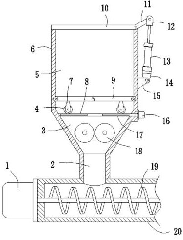
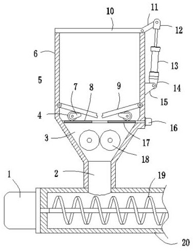
[0022]Such asFigure 1-2As shown, an extruding device for an optical cable production line includes a base 20 of an extruder. The base 20 is horizontally connected with an extrusion screw 19, and the extrusion screw 19 is installed on the base 20. The geared motor 1 on the upper drive rotates, the base 20 is provided with a feed port 2, and the upper port of the feed port 2 is connected with a feed bin 6 through it. The feed bin 6 has two symmetrical hinges along its axis. Two baffle plates 9, when the two baffle plates 9 are rotated to a horizontal state, the inside of the feeding bin 6 is divided into a storage cavity 5 and a crushing cavity 3 from top to bottom. The two baffle plates 9 is driven by the drive assembly to rotate in the opposite direction along the hinge joint with the inner wall of the feeding bin 6, so that the opposite ends of the two form a blanking space for the fiber optic cable raw materials to enter the crushing cavity 3, and the top of the feeding bin 6 is o...


PUM


Abstract

The invention discloses an extrusion molding device for an optical cable production line. The extrusion molding device comprises a machine base, an extrusion molding screw rod, a speed reducing motor,a feeding hole, a feeding bin, material baffle plates, a material storage cavity and a crushing cavity, wherein the two material baffle plates are driven by a driving assembly to synchronously and reversely rotate along the part hinged to the inner wall of the feeding bin, a material falling space for allowing an optical cable raw material to enter the crushing cavity is formed at the opposite ends of the material baffle plates, a cover plate is hinged to the top of the feeding bin, and two extrusion rollers are rotatably connected to the interior of the crushing cavity. The extrusion moldingdevice has the beneficial effects that the two extrusion rollers are arranged to extrude and crush the optical cable raw material, so that the particle size of the optical cable raw material is reduced, extrusion molding of the extrusion molding screw rod is facilitated, and the two material baffle plates are arranged and driven by the driving assembly to synchronously and reversely rotate so that the opposite ends of the two material baffle plates can form the material falling space for allowing the optical cable raw material to circulate, the circulation amount of the optical cable raw material is limited, and the blocking phenomenon of the optical cable raw material is further avoided.

Description

Technical field[0001]The invention relates to the field of extrusion equipment, in particular to an extrusion device for an optical cable production line.Background technique[0002]Extruder is an important plastic machinery, most of the production and manufacture of plastic products can be realized by extrusion molding. The motor of the extruder is an important part of the extruder. It is the prime mover of the extruder and provides the large thrust required by the screw of the extruder. A low-speed and high-torque permanent magnet direct drive motor is designed for the current universal 90mm screw extruder. It has many advantages such as high efficiency, high power density, good energy saving, high reliability, and high control accuracy. When the plastic machine is working, the plastic in the barrel is a high-temperature molten plastic colloid, and the permanent magnet motor is directly connected with the extruder screw, which will have an adverse effect on the temperature rise of t...

Claims


Application Information

Patent Timeline
Patent Type & Authority Applications(China)
IPC IPC(8): B29C48/285B29C48/06B29L31/34
CPCB29C48/287B29C48/288B29C48/297B29C48/06B29L2031/3462
Inventor 卢立建
Owner 湖南中科光电有限公司
Why Eureka
Try Eureka