Building wall thermal resistance field test device and method

A technology for on-site testing and building walls, applied in the field of building wall thermal resistance testing, can solve the problems of unfavorable one-dimensional heat transfer, rapid establishment of heat transfer, large cooling/heating energy consumption, inconvenient installation and operation, etc., and save manpower for testing cost, improve the accuracy of results, and reduce the effect of loss

Pending Publication Date: 2021-01-15
TSINGHUA UNIV
View PDF0 Cites 3 Cited by
  • Summary
  • Abstract
  • Description
  • Claims
  • Application Information

AI Technical Summary

Problems solved by technology

[0007] The hot box method and the hot and cold box method can be tested without seasonal restrictions. However, due to the local heating of the wall, the actual wall heat conduction process has a three-dimensional effect of lateral heat loss, which is not conducive to the rapid establishment of one-dimensional heat transfer. Will cause errors in the test results under the one-dimensional assumption
In order to weaken the influence of three-dimensional heat transfer, the box equipment is very large (the area is at least 1m×1m), and the wall site may not have enough suitable space for large-area heating due to thermal bridges formed by doors, windows, beams, etc., resulting in installation and operation. inconvenient
In addition, the large volume of the cold / hot box also causes a large amount of cooling / heating energy consumption during the detection process

Method used


Image

  • Building wall thermal resistance field test device and method
  • Building wall thermal resistance field test device and method
  • Building wall thermal resistance field test device and method

Examples


Embodiment Construction

[0032] In order to make the object, technical solution and advantages of the present invention clearer, the present invention will be further described in detail below in conjunction with the accompanying drawings and embodiments. It should be understood that the specific embodiments described here are only used to explain the present invention, and do not limit the protection scope of the present invention.

[0033] In order to better understand the present invention, an application example of a field testing device and method for building wall thermal resistance proposed by the present invention will be described in detail below.

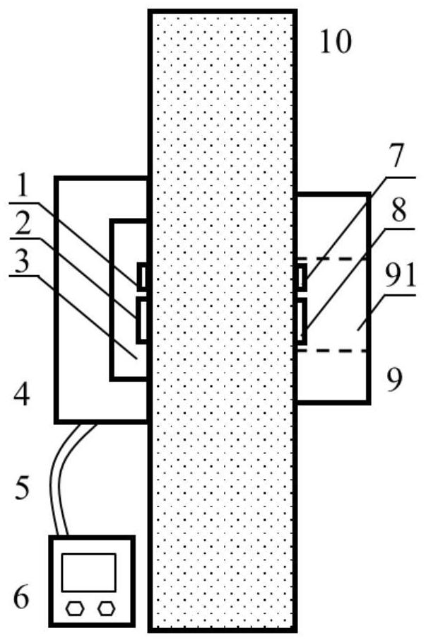
[0034] An on-site testing device for building wall thermal resistance in an embodiment of the present invention, its overall structure can be found in figure 1 , including heating plate 3, two temperature sensors (1 and 7), two heat flow sensors (2 and 8) and two heat preservation plates (4 and 9). Wherein, the first temperature sensor 1 and the ...


PUM


Abstract

The invention provides a building wall thermal resistance field test device and method. The test device comprises two heating plates, two temperature controllers, two temperature sensors, two heat flow sensors and two insulation plates. The first temperature sensor, the first heat flow sensor, the heating plate and the first heat preservation plate are all attached to the hot side of a measured wall, the second temperature sensor, the second heat flow sensor and the second heat preservation plate are all attached to the cold side of the measured wall, and a through hole serving as a heat flowone-dimensional channel is formed in the middle of the second heat preservation plate. The second temperature sensor and the second heat flow sensor are positioned in the through hole. The testing method comprises the following steps: quantitatively determining the size of the one-dimensional heat transfer area on the cold side and the hot side of the wall, measuring and recording the surface temperature of the one-dimensional heat transfer area on the cold side and the hot side of the wall and the density of heat flow passing through the one-dimensional heat transfer area, and calculating theequivalent thermal resistance of the wall. By arranging the one-dimensional channel facilitating centralized passing of heat flow and adopting a two-stage heating method, steady-state heat transfer can be rapidly established, and the test time is effectively shortened.

Description

technical field [0001] The invention belongs to the field of thermal resistance testing of building walls, in particular to an on-site testing device and method for testing the thermal resistance of building walls. Background technique [0002] my country's building energy consumption accounts for more than 20% of the country's total energy consumption, and the total building area is huge. Building energy conservation has become an inevitable trend in the construction industry. The energy consumption of heating, ventilation and air conditioning accounts for a large part of building energy consumption, and 20%-50% of the energy consumption of heating and cooling is caused by the heat transfer of the building envelope. The building wall is the main enclosure structure component, and the thermal resistance is an important index to measure the thermal insulation performance of the wall, and it is also the main basis for calculating the heat dissipation of the wall. [0003] The...

Claims


Application Information

Patent Timeline
IPC IPC(8): G01N25/20
CPCG01N25/20
Inventor 王馨寇方铖莫金汉李浩
Owner TSINGHUA UNIV
Why Eureka
Try Eureka