Two-dimensional optical transfer function measuring device and method

A technology of optical transfer function and measuring device, which is applied in the direction of testing optical properties, etc., can solve problems such as expensive, only one-dimensional results, and diffusion function deviation, and achieve the effects of convenient operation, fast measurement, and simple structure

Inactive Publication Date: 2021-01-15
SHANGHAI INST OF OPTICS & FINE MECHANICS CHINESE ACAD OF SCI
View PDF4 Cites 0 Cited by
  • Summary
  • Abstract
  • Description
  • Claims
  • Application Information

AI Technical Summary

Problems solved by technology

Most of the existing MTF measuring instruments are based on the knife-edge digital image Fourier analysis method, which has a single direction of measurement results and only one-dimensional results; the deviation of the diffusion function is easily affected by various errors; the signal strength in the high frequency band is so small that the signal The noise ratio is too small; the shortcomings such as PTF cannot be measured, and the price is too expensive

Method used


Image

  • Two-dimensional optical transfer function measuring device and method
  • Two-dimensional optical transfer function measuring device and method
  • Two-dimensional optical transfer function measuring device and method

Examples


Embodiment 1

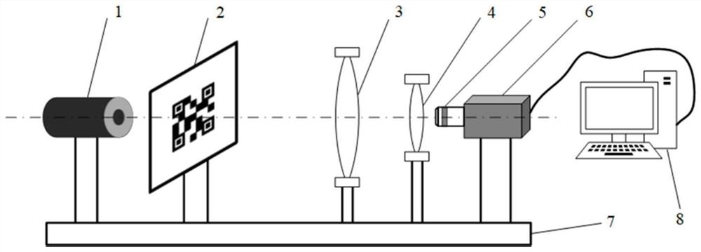
[0034] For common photography, monitoring, and industrial imaging lenses, that is, the infinite-finite conjugate lens to be tested, the light source 1, the random coding plate 2, the collimator 3, the lens to be tested 4, the microscope 5, and the two-dimensional photoelectric detection The detectors 6 are all fixed on the base 7, and adjusted to align the optical axes, and focus until the image is clear. Select the light source 1 with the same wavelength according to the measurement requirements, and the light source 1 is uniformly irradiated on the random coding plate 2, and the random coding plate 2 is located at the front focal plane of the collimating mirror 3 , imaged at infinity by the collimating mirror 3, according to the F-number and the measurement requirement wavelength of the lens to be tested 4, determine its cut-off frequency, the cut-off frequency is 1 / (wavelength*F number), thus select The random coding plate 2 whose spatial frequency (reciprocal of size) is h...

Embodiment 2

[0048] For the lens 4 to be tested whose working distance is finite, that is, the finite-finite conjugate, the collimating mirror 3 is not needed, and the random coding plate 2 is directly placed on the lens to be tested. The measurement of the lens 4 requires the position. The following measurement steps are consistent with Example 1.

Embodiment 3

[0050] For the infinity-infinity conjugated lens 4 to be measured, such as a telescope, a relay lens is added after the lens to be measured 4, the overall equivalent of the lens 4 to be measured in Embodiment 1, and other The measurement procedure is consistent with embodiment 1.


PUM


Abstract

The invention discloses a two-dimensional optical transfer function measurement device and method. The device comprises a light source, a random coding plate, a microscope, a two-dimensional photoelectric detector, a computer and data acquisition and processing software, wherein the light source illuminates the random coding plate to serve as a target, an auxiliary lens is installed in a light path according to the type of a to-be-detected lens to be matched with the to-be-detected lens to image the target, the image is amplified by a microscope, and finally a two-dimensional photoelectric detector records the formed image; different random coded images are replaced for multiple times in one-time measurement, multiple images are recorded, Fourier transform is carried out on the recorded images and known coded images, and a two-dimensional optical transfer function containing all aperture directions is finally calculated in Fourier frequency domain scanning iteration. According to the device, based on the frequency domain scanning technology, two-dimensional PTF is accurately measured while high-precision and large-range frequency two-dimensional MTF measurement is realized; the device can be used for lens detection and can also play a great role in promoting image quality improvement.

Description

technical field [0001] The present invention relates to the field of optical system imaging measurement, specifically a two-dimensional optical transfer function (OTF, Optical Transfer Function), including modulation transfer function (MTF, Modulation Transfer Function) and phase transfer function (PTF, Phase Transfer Function) Apparatus and methods. Background technique [0002] The evaluation of the imaging quality of an optical system has always been a concern in the field of optics. Among many image quality evaluation methods, Modulation Transfer Function (MTF) can accurately, objectively and quantitatively evaluate the imaging quality of optical systems, and is recognized as the most effective and comprehensive method at present. As the need for high-quality, high-resolution optical systems becomes more common, optical designers and scientists are increasingly using MTF to characterize optical system-related properties. Regardless of large-scale astronomical telescope...

Claims


Application Information

Patent Timeline
Patent Type & Authority Applications(China)
IPC IPC(8): G01M11/02
CPCG01M11/02
Inventor 刘诚浦东潘兴臣陶华朱健强
Owner SHANGHAI INST OF OPTICS & FINE MECHANICS CHINESE ACAD OF SCI
Why Eureka
Try Eureka