Fuel oil high-temperature vaporization oil supply system of fuel oil engine

A fuel engine and fuel supply system technology, applied in combustion engines, internal combustion piston engines, engine components, etc., can solve the problems of insufficient vaporization, insufficient vaporization time, and incomplete combustion.

Pending Publication Date: 2021-01-15
王明中
View PDF0 Cites 0 Cited by
  • Summary
  • Abstract
  • Description
  • Claims
  • Application Information

AI Technical Summary

Problems solved by technology

[0002] The engine has become an indispensable power machine in the industry and has been widely used in automobiles. The fuel supply system of traditional fuel engines mainly adopts two types: carburetor type and direct injection type. The former uses a carburetor to mix fuel with air. After that, the mixed gas is formed and enters the cylinder. The latter uses high pressure to directly inject fuel into the intake pipe or cylinder. When the fuel is burned, it needs to be evaporated into oil vapor and mixed with air before it can proceed. Since the engine rotates at a very high speed, when the speed reaches 3000 When the cylinder rotates per minute, the cylinder will carry out 1500 suction injection actions per minute. The fuel injection speed of 25 times per second results in a serious shortage of time for the fuel to enter the cylinder to vaporize, resulting in an extremely insufficient degree of vaporization. Larger fuel particles at a deflagration rate of 25 times per second will lead to insufficient combustion work or incomplete combustion. When the engine is suddenly loaded, the incompletely vaporized mixture cannot burn with maximum efficiency, seriously affecting The power output of the engine and the emission of more pollutants

Method used


Image

  • Fuel oil high-temperature vaporization oil supply system of fuel oil engine
  • Fuel oil high-temperature vaporization oil supply system of fuel oil engine
  • Fuel oil high-temperature vaporization oil supply system of fuel oil engine

Examples


Embodiment Construction

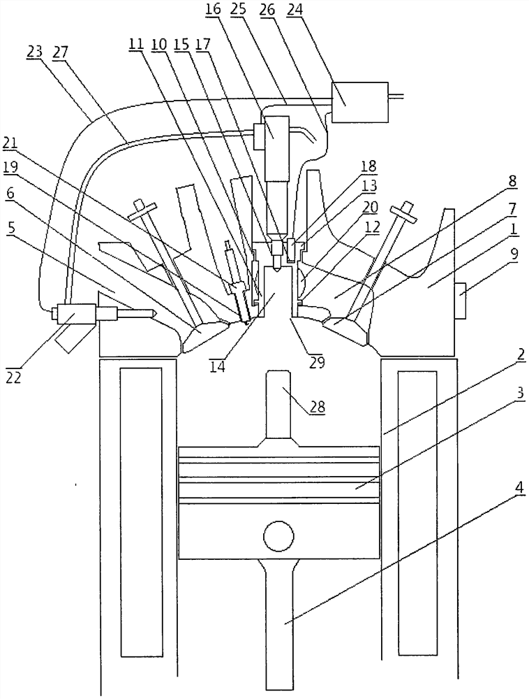
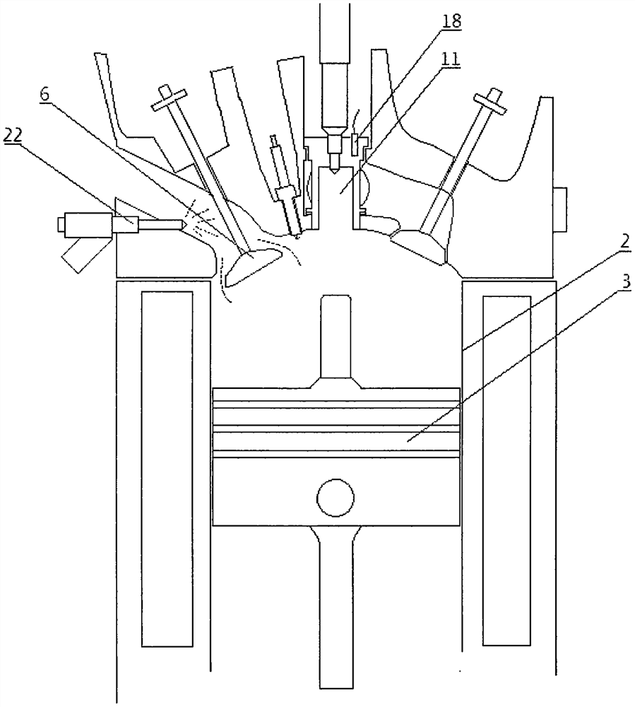
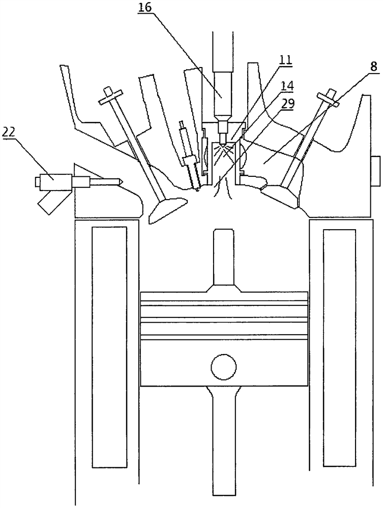
[0011] pass figure 1 It can be seen that the cylinder head (1) is installed on the top of the cylinder (2), and a piston (3) is arranged in the cylinder. When the engine is working, the crankshaft and the connecting rod (4) drive the piston to move up and down in the cylinder to perform suction, During the working strokes of compression, work, and exhaust, the air enters the cylinder through the intake port (5) and the intake valve (6), and the exhaust gas after combustion enters the exhaust port (8) through the exhaust valve (7) and is exhausted. The central position of the cylinder head (1) is provided with an evaporation chamber installation hole (10), the upper end of the evaporation chamber installation hole is installed with a high-temperature evaporation chamber (11), and the lower end of the high-temperature evaporation chamber is sealed under the evaporation chamber. The head (12) is sealed with the installation hole (10) of the evaporation chamber, and the upper end ...


PUM


Abstract

The invention relates to the field of fuel oil engines, in particular to an oil supply technology adopting intake pipe injection and in-cylinder direct injection, and discloses a fuel oil high-temperature vaporization oil supply system of a fuel oil engine. In the system, heat discharged by an engine exhaust passage is used for heating a high-temperature evaporation chamber, and fuel oil is instantly vaporized into oil vapor by the heat after being injected into the high-temperature evaporation chamber, and then enters an air cylinder to be combusted to act. The high-temperature evaporation chamber is arranged in the center of the top end of an engine air cylinder cover and located in the middle of the exhaust passage, an evaporation chamber oil injector is arranged at the top of the high-temperature evaporation chamber, an intake pipe oil injector is arranged on an intake pipe, oil injection circuits of the two oil injectors are connected with an oil injection circuit converter, and the line inlet end of the oil injection circuit converter is connected with an oil injection power supply of an engine control computer. When the system works, the high-pressure atomized fuel oil is instantaneously evaporated and vaporized under the action of the heat when being injected to the inner wall of the high-temperature evaporation chamber, and the oil vapor generated after vaporization enters the air cylinder at the lower end to be ignited and combusted to act, so that the working performance of high-temperature vaporization oil supply is realized.

Description

technical field [0001] The invention relates to the field of fuel engines, in particular to a fuel supply technology using intake pipe injection and in-cylinder direct injection. Background technique [0002] The engine has become an indispensable power machine in the industry and has been widely used in automobiles. The fuel supply system of traditional fuel engines mainly adopts two types: carburetor type and direct injection type. The former uses a carburetor to mix fuel with air. After that, the mixed gas is formed and enters the cylinder. The latter uses high pressure to directly inject fuel into the intake pipe or cylinder. When the fuel is burned, it needs to be evaporated into oil vapor and mixed with air before it can proceed. Since the engine rotates at a very high speed, when the speed reaches 3000 When the cylinder rotates per minute, the cylinder will carry out 1500 suction injection actions per minute. The fuel injection speed of 25 times per second results in ...

Claims


Application Information

Patent Timeline
IPC IPC(8): F02M31/18F01N5/02F02F1/24
CPCF01N5/02F02F1/24F02F1/242F02M31/18Y02T10/12
Inventor 王明中
Owner 王明中
Why Eureka
Try Eureka