Uplift pile
The invention relates to a technology of anti-uplift piles and pile heads, which is applied to anti-uplift piles. field, it can solve problems such as low buoyancy of structural strength, loss of pull-out resistance, and impact on pile pressure-bearing performance, and achieve the effects of reducing difficulty, improving pull-out resistance, and convenient docking
- Summary
- Abstract
- Description
- Claims
- Application Information
AI Technical Summary
Problems solved by technology
Method used
Image
Examples
Embodiment 1
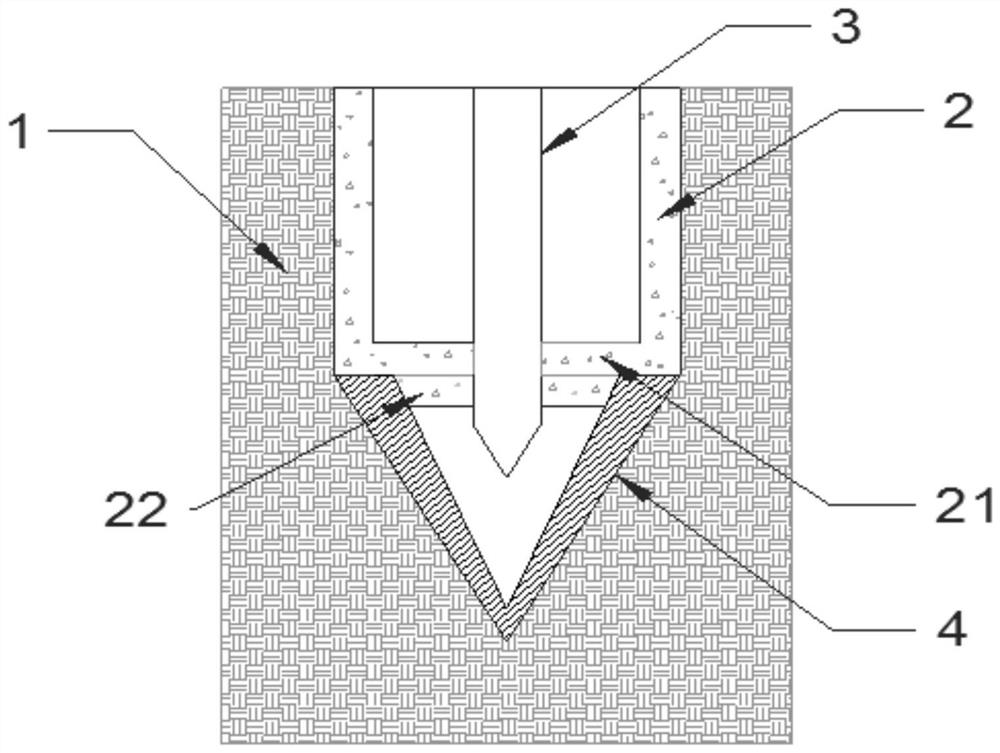
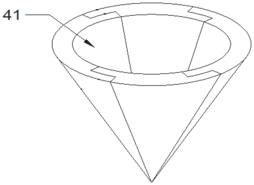
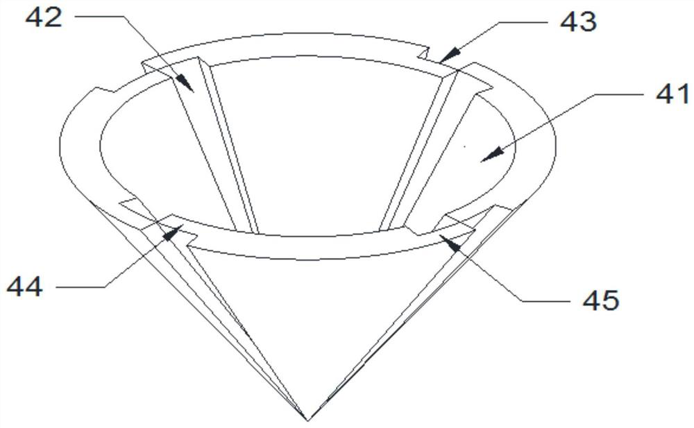
[0042] Such as figure 1 As shown, the uplift pile according to the present invention includes a prefabricated pile body 2. The pile body 2 in this embodiment is preferably a cylindrical structure. 21 coaxial boss 22; the upper surface of the bottom plate 21 and the corresponding position on the lower surface of the boss 22 are provided with installation holes through the bottom plate 21 and the boss 22, and a one-way grouting pipe 3 is inserted in the installation hole, and the one-way grouting The outer wall of the pipe 3 is sealed with the inner wall of the installation hole; the position where the one-way grouting pipe 3 contacts the upper surface of the bottom plate 21, and the position where the one-way grouting pipe 3 contacts the lower surface of the boss 22 are all equipped with a clamping structure to ensure The one-way grouting pipe 3 remains stable during the high-pressure grouting process and will not be detached from the installation hole. The clamping structure i...
Embodiment 2
[0048] In this embodiment, on the basis of Embodiment 1, the anti-extraction pile head 4 has been improved as follows:
[0049] Such as Figure 6 , 7 As shown, the outer wall of each sub-shell 41 is vertically provided with a side plate 46, the side plate 46 is perpendicular to the outer wall of the sub-shell 41, and the side plate 46 is a triangular plate including a bottom 461, a side 462, and a hypotenuse; the bottom of the side plate 46 One end of the edge 461 away from the cone point of the pile head 4 is not higher than the other end of the bottom edge 461 of the side plate 46, and is not higher than the cone point of the pile head 4. The other end of the bottom edge 461 and the cone point of the pile head 4 are all equal in height; the side plate 46 can provide support for the spliced pile head 4, so that it can be stably placed vertically on the ground at the piling point without causing the shell The self-weight of 41 is scattered, thereby ensuring convenient dock...
Embodiment 3
[0051] In this embodiment, on the basis of Embodiment 1, the anti-extraction pile head 4 has been improved as follows:
[0052] Such as Figure 9 , 10 As shown, the top of the sub-shell 41 is a fan-shaped plate 47 structure, and the two ends of the fan-shaped plate 47 near the two sides of the sub-shell 41 are respectively provided with a lower half plate 471 and an upper half plate 472, and the lower half plate 471 and the upper half plate 472. The thickness is half of the thickness of the other parts of the fan-shaped plate 47. At the same time, the upper end of the conical wall of the sub-shell 41 corresponding to the upper half-plate 472 is provided with a notch 411 for installing the lower half-plate 471 to ensure that the lower part of the two adjacent sub-shells 41 The half plate 471 and the upper half plate 472 can be clamped together, and the four sub-shells 41 can be spliced together to form a complete pile head 4 with an annular roof structure. Such as Figure ...
PUM
 Abstract
Description
Claims
Application Information
 - R&D
- Intellectual Property
- Life Sciences
- Materials
- Tech Scout
- Unparalleled Data Quality
- Higher Quality Content
- 60% Fewer Hallucinations
Browse by: Latest US Patents, China's latest patents, Technical Efficacy Thesaurus, Application Domain, Technology Topic, Popular Technical Reports.
© 2025 PatSnap. All rights reserved.Legal|Privacy policy|Modern Slavery Act Transparency Statement|Sitemap|About US| Contact US: help@patsnap.com


