Automatic water quality disinfection and sterilization device adopting ultraviolet disinfection
A technology of ultraviolet light and water quality, applied in the direction of oxidized water/sewage treatment, multi-stage water treatment, chemical instruments and methods, etc., can solve the problems of waste of sterilization time, ozone cannot be fully contacted with water quality, bacteria cannot be completely eliminated, etc., to achieve Improve the environmental protection effect of the device
- Summary
- Abstract
- Description
- Claims
- Application Information
AI Technical Summary
Problems solved by technology
Method used
Image
Examples
Embodiment 1
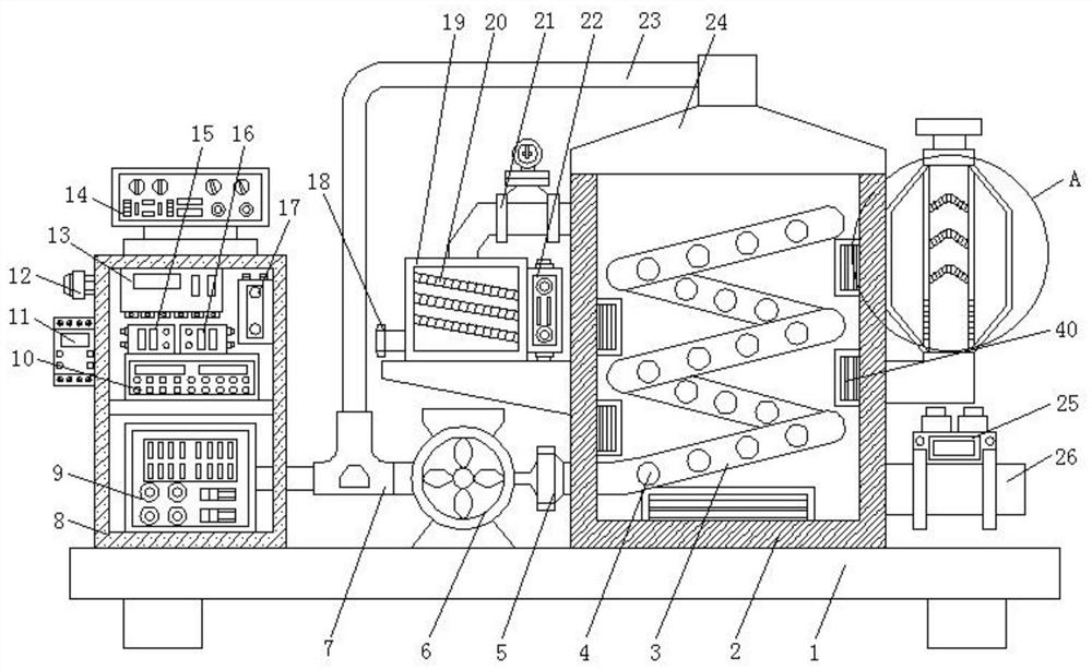
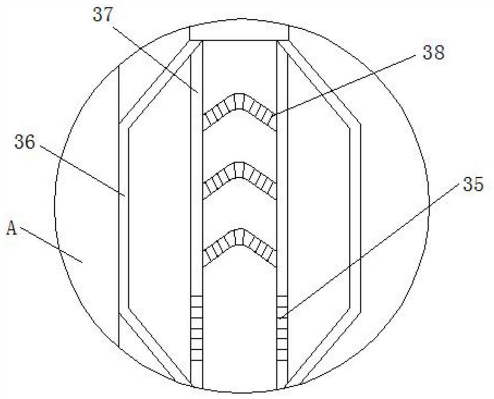
[0028] Such as Figure 1-Figure 5 As shown, the present invention provides a kind of automatic water quality killing device that adopts ultraviolet disinfection, comprises base plate 1, and the right side of base plate 1 top surface is fixedly connected with organic body 2, and the side of body 2 inner cavity is fixedly connected with ultraviolet light tube 40, and the body The top surface of 2 is fixedly connected with wind-collecting hood 24, and the side of wind-collecting hood 24 is fixedly connected with air return pipe 23, and one end of air return pipe 23 is fixedly connected with tee pipe 7, and the right side of tee pipe 7 is fixedly connected with guide pipe 7. The fan 6 and the output end of the induced draft fan 6 are fixedly connected with a one-way valve 5, and the right side of the one-way valve 5 is fixedly connected with a conduit 3, and one end of the conduit 3 extends to the inner cavity of the body 2 and is wound inside the body 2, The left side of the top ...
Embodiment 2
[0033] Such as figure 1 , 5 As shown, on the basis of Embodiment 1, the present invention provides a technical solution: the middle part of the inner cavity of the chassis 8 is fixedly connected with a central control machine 10, and the top surface of the central control machine 10 is fixedly connected with a receiving module 15 and a transmitting module 16 , the output end of the receiving module 15 is connected with the input end of the central control machine 10, the output end of the central control machine 10 is communicated with the input end of the transmitting module 16, and the top surface of the cabinet 8 inner cavity is fixedly connected with the control module 13, the cabinet 8 The left side of the chassis 8 is fixedly connected with a timer 11, the left side of the chassis 8 is fixedly connected with a buzzer 12 above the timer 11, the right side of the inner cavity of the chassis 8 is fixedly connected with a power supply 17, and the top surface of the chassis 8...
Embodiment 3
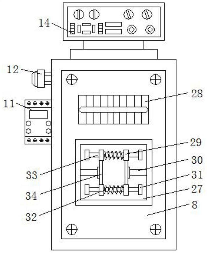
[0035] Such as figure 1 , 2 As shown, on the basis of Embodiment 1 and Embodiment 2, the present invention provides a technical solution: preferably, the top of the front of the cabinet 8 is provided with a cooling groove 28, and the bottom surface of the front of the cabinet 8 is movably socketed with a sealing plate 27, The front of the sealing plate 27 is fixedly connected with a fixed plate 31, and the side of the fixed plate 31 is fixedly connected with a straight bar 33, and the straight bar 33 is movably socketed with a slide block 29. The number of slide blocks 29 is four, and the four slide blocks 29 Evenly distributed on the two straight rods 33, a stage clip 32 is fixedly connected between the two sliders 29, the bottom surface of the slider 29 is fixedly connected with a connecting plate 34, and the side of the connecting plate 34 is fixedly connected with a clamping rod 30, the chassis 8 The inner wall of the cover is provided with a clamping hole, and one end of...
PUM
 Abstract
Description
Claims
Application Information
 - R&D
- Intellectual Property
- Life Sciences
- Materials
- Tech Scout
- Unparalleled Data Quality
- Higher Quality Content
- 60% Fewer Hallucinations
Browse by: Latest US Patents, China's latest patents, Technical Efficacy Thesaurus, Application Domain, Technology Topic, Popular Technical Reports.
© 2025 PatSnap. All rights reserved.Legal|Privacy policy|Modern Slavery Act Transparency Statement|Sitemap|About US| Contact US: help@patsnap.com


