Multi-picture monitoring method, device and system
A monitoring device and monitoring system technology, which is applied to closed-circuit television systems, components of television systems, televisions, etc., can solve the problems of reducing the user experience of customers and being unable to monitor the input video source in real time, so as to reduce the user experience of customers, Improve customer experience and improve scalability
- Summary
- Abstract
- Description
- Claims
- Application Information
AI Technical Summary
Problems solved by technology
Method used
Image
Examples
no. 1 example
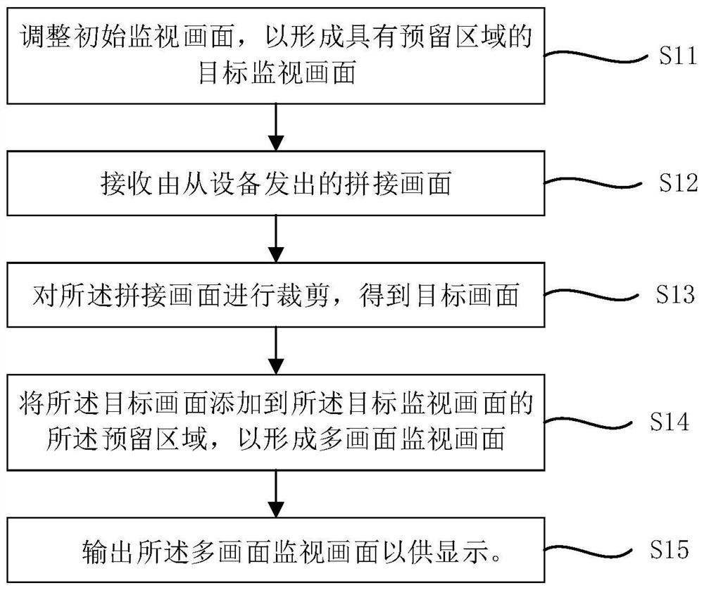
[0049] see figure 1 , the first embodiment of the present invention proposes a multi-screen monitoring method. Such as figure 1 As shown, the multi-screen monitoring method includes, for example, steps S11 to S15.
[0050] Step S11: adjusting the initial monitoring picture to form a target monitoring picture with a reserved area;
[0051] Step S12: receiving the splicing picture sent by the slave device;
[0052] Step S13: cutting out the spliced picture to obtain a target picture;
[0053] Step S14: adding the target picture to the reserved area of the target monitoring picture to form a multi-screen monitoring picture;
[0054] Step S15: Outputting the multi-screen surveillance images for display.
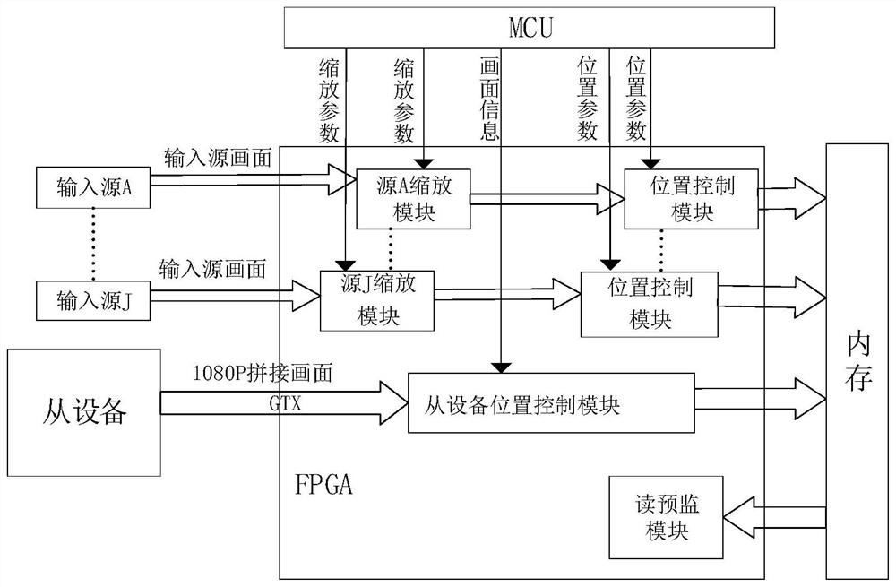
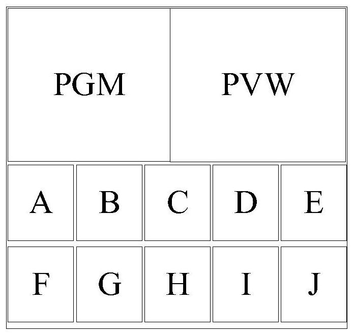
[0055] Specifically, the initial monitoring picture and the target monitoring picture mentioned in step S11 include, for example, an input source picture, a PGM (Program, on-air picture) and a PVW (preview, a preview picture). Among them, the input source picture, the p...
no. 2 example
[0071] see Figure 4 , the second embodiment of the present invention provides a multi-screen monitoring device. Such as Figure 4 As shown, the multi-screen monitoring device 20 includes, for example, a screen adjustment module 21 , a screen receiving module 22 , a screen cropping module 23 , a screen adding module 24 and a screen output module 25 .
[0072] Wherein, the picture adjustment module 21 is used for adjusting the initial monitoring picture to form a target monitoring picture with a reserved area. The picture receiving module 22 is used for receiving the spliced picture sent by the slave device. The picture clipping module 23 is used for clipping the spliced picture to obtain a target picture. The picture adding module 24 is used for adding the target picture to the reserved area of the target monitoring picture to form a multi-picture monitoring picture. The picture output module 25 is used to output the multi-picture monitoring picture for display.
[...
no. 3 example
[0075] see Figure 5 , the third embodiment of the present invention provides a multi-screen monitoring method. Such as Figure 5 As shown, the multi-screen monitoring method includes, for example, steps S31 to S32.
[0076] Step S31: performing scaling and splicing processing on the target video source to form a spliced picture including the target picture;
[0077] Step S32: Send the spliced picture and the picture information associated with the target picture to a master device, so that the master device executes steps S321 to S324.
[0078] Such as Figure 6 As shown, steps S321 to S324 are, for example:
[0079] Step S321: adjusting the initial monitoring picture according to the picture information to form a target monitoring picture with a reserved area;
[0080] Step S322: Cutting out the spliced picture according to the picture information to obtain the target picture;
[0081] Step S323: adding the target picture to the reserved area of the target moni...
PUM
 Abstract
Description
Claims
Application Information
 - R&D Engineer
- R&D Manager
- IP Professional
- Industry Leading Data Capabilities
- Powerful AI technology
- Patent DNA Extraction
Browse by: Latest US Patents, China's latest patents, Technical Efficacy Thesaurus, Application Domain, Technology Topic, Popular Technical Reports.
© 2024 PatSnap. All rights reserved.Legal|Privacy policy|Modern Slavery Act Transparency Statement|Sitemap|About US| Contact US: help@patsnap.com


