
Spacecraft surface heat flow non-contact measurement method based on vacuum thermal test

A technology of non-contact measurement and vacuum thermal test, applied in the field of heat flow measurement and non-contact measurement of heat flow on the surface of spacecraft, it can solve the problems of measurement error, uneven distribution of heat flow density, and inability to guarantee the accuracy of heat flow simulation, and achieve accurate heat flow values. , the effect of improving the effectiveness

Active Publication Date: 2021-01-12
BEIJING INST OF SPACECRAFT ENVIRONMENT ENG
View PDF5 Cites 3 Cited by
  • Summary
  • Abstract
  • Description
  • Claims
  • Application Information

AI Technical Summary

Problems solved by technology

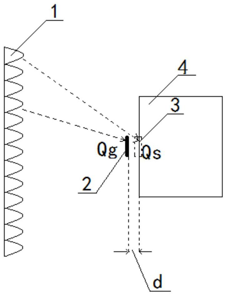
However, in the vacuum thermal test itself, there is a phenomenon that the heat flux density distribution on the entire heated surface is uneven; in non-contact measurement, for the same heating zone, when the heat flow meter installation surface and the surface to be tested are not in the same plane, the distance between the two surfaces There is an installation distance, which causes measurement errors. Therefore, the installation position and arrangement quantity of the heat flow meter will affect the accuracy of the heat flow simulation
At present, when the heat flow meter is installed on the bracket for non-contact measurement, the above factors that affect the measurement accuracy are not fully considered, and the accuracy of the heat flow simulation cannot be guaranteed.

Method used


Image

  • Spacecraft surface heat flow non-contact measurement method based on vacuum thermal test
  • Spacecraft surface heat flow non-contact measurement method based on vacuum thermal test
  • Spacecraft surface heat flow non-contact measurement method based on vacuum thermal test

Examples


Embodiment Construction

[0035] The present invention will be further described in detail below in conjunction with the accompanying drawings and embodiments. It should be understood that the specific embodiments described here are only used to explain related inventions, rather than to limit the invention. It should also be noted that, for ease of description, only parts related to the invention are shown in the drawings.

[0036] It should be noted that, in the case of no conflict, the embodiments of the present invention and the features in the embodiments can be combined with each other. The present invention will be described in detail below with reference to the accompanying drawings and examples.

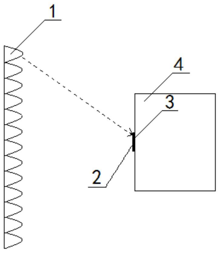
[0037] The present invention proposes a non-contact measurement method for heat flow on the surface of a spacecraft based on a vacuum thermal test for the measurement of heat flow on the surface of a spacecraft that cannot be equipped with a heat flow meter in a vacuum thermal test, such as figure...


PUM


Abstract

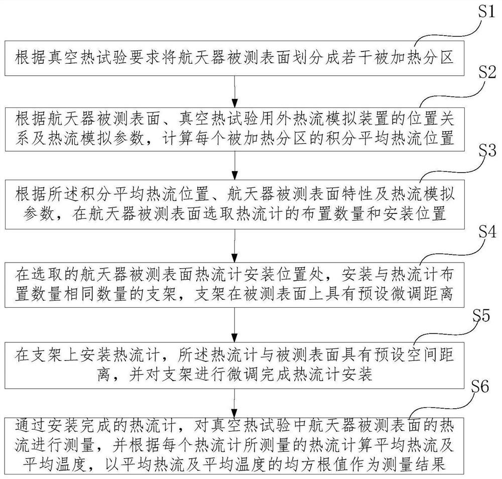
The invention provides a spacecraft surface heat flow non-contact measurement method based on a vacuum thermal test, which is used for solving the problem of inaccurate non-contact heat flow measurement in the prior art. The non-contact measurement method comprises the following steps: on the basis that a measured surface is divided into a plurality of heated subareas, calculating the integral average heat flow position of each heated subarea, selecting the arrangement number and installation positions of heat flow meters and the spatial distance between the heat flow meters and the measured surface according to the integral average heat flow positions, installing the heat flow meters through a bracket, measuring the heat flow of the measured surface of the spacecraft in the vacuum thermaltest, calculating the average heat flow and the average temperature according to the heat flow measured by each heat flow meter, and taking the root-mean-square values of the average heat flow and the average temperature as measurement results. The heat flow meters do not need to make contact with the surface of the spacecraft, heat flow reaching the surface of the spacecraft is accurately measured, the heat flow meter is suitable for the spacecraft surface where a fixed heat flow meter cannot be installed in a vacuum thermal test, and effectiveness of the spacecraft vacuum thermal test is improved.

Description

technical field [0001] The invention belongs to the field of spacecraft vacuum heat test, and in particular relates to a non-contact measurement method for heat flow on a surface of a spacecraft based on a vacuum heat test, which is used for heat flow measurement when the mounting surface of a heat flow meter is not coplanar with the surface to be measured. Background technique [0002] Before the spacecraft is used, it needs to conduct a performance test through a vacuum thermal simulation test. In order to simulate the heat flow of the spacecraft outside the orbit during the vacuum thermal test, it is necessary to heat the surface of the spacecraft with a heating cage, an infrared lamp array or a heating plate to simulate the solar radiation and the earth radiation received or absorbed by the spacecraft when it is in orbit. According to the external heat flow, in order to accurately simulate the heat flow distribution on the surface of the spacecraft, it is necessary to me...

Claims


Application Information

Patent Timeline
IPC IPC(8): G01M99/00
CPCG01M99/002
Inventor 孙玉玮林博颖李日华赵欣周宇鹏肖福根杨晓媛
Owner BEIJING INST OF SPACECRAFT ENVIRONMENT ENG
Learn More