Eureka AIR delivers breakthrough ideas for toughest innovation challenges, trusted by R&D personnel around the world.

Phase detection system and method based on dynamic response time measurement method

A time measurement and dynamic response technology, applied in the field of signal processing, can solve the problems of cumbersome measurement process, small application range of signal frequency, inability to achieve high measurement resolution, etc., to achieve the effect of high measurement resolution and reduced signal transmission rate requirements

Active Publication Date: 2021-11-05
TSINGHUA UNIV
View PDF11 Cites 0 Cited by
  • Summary
  • Abstract
  • Description
  • Claims
  • Application Information

AI Technical Summary

Problems solved by technology

[0009] In view of the above problems, the purpose of the present invention is to provide a phase detection system and method based on the dynamic response time measurement method to solve the problems of the existing phase measurement methods that cannot achieve high measurement resolution, the signal frequency application range is small, and the measurement process Complexity and high cost

Method used


Image

  • Phase detection system and method based on dynamic response time measurement method
  • Phase detection system and method based on dynamic response time measurement method
  • Phase detection system and method based on dynamic response time measurement method

Examples


Embodiment Construction

[0036] In the following description, for purposes of explanation, numerous specific details are set forth in order to provide a thorough understanding of one or more embodiments. It may be evident, however, that these embodiments may be practiced without these specific details. In other instances, well-known structures and devices are shown in block diagram form in order to facilitate describing one or more embodiments.

[0037] In order to describe in detail the phase detection system and method based on the dynamic response time measurement method of the present invention, specific embodiments of the present invention will be described in detail below in conjunction with the accompanying drawings.

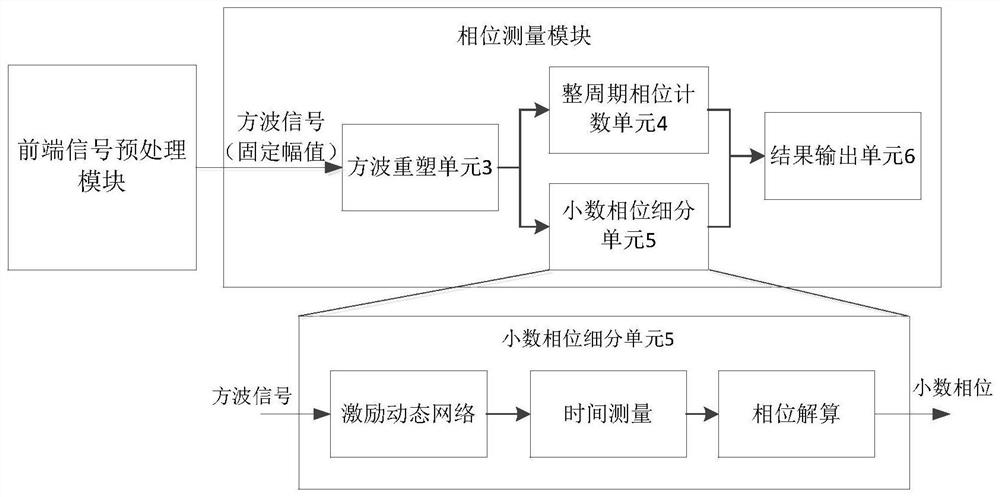
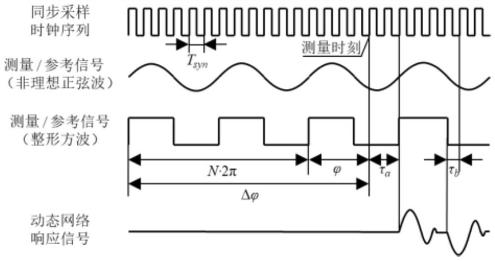
[0038] figure 1 and figure 2 The logic of the phase detection system based on the dynamic response time measurement method according to the embodiment of the present invention is shown from different angles.

[0039] Such as figure 1 and figure 2 Commonly shown, the phase de...


PUM


Abstract

The invention provides a phase detection system and method based on a dynamic response time measurement method, wherein the system includes a front-end signal preprocessing module and a phase measurement module connected to the front-end signal preprocessing module; wherein the front-end signal preprocessing module includes a phase connection A photodetector and a square wave shaping unit, the photodetector is used to receive the signal to be detected, and convert the received signal to be detected into an electrical signal, and the square wave shaping unit is used to convert the electrical signal into a square wave signal with a fixed amplitude , and transmitted to the phase measurement module; the phase measurement module is used to analyze and process the square wave signal to obtain phase change information of the signal to be detected. The invention can expand the frequency range of the detection signal, has high measurement resolution, and is suitable for precision and ultra-precision measurement fields.

Description

technical field [0001] The present invention relates to the technical field of signal processing based on interferometry technology, and more specifically, to a phase detection system and method based on a dynamic response time measurement method. Background technique [0002] At present, the optical system of a laser interferometer usually adopts a Michelson interferometer structure. Taking a dual-frequency laser interferometer as an example, the dual-frequency orthogonally polarized laser light emitted from the laser is split by a polarization beam splitter prism, and then incident on a fixed mirror all the way to form The reference arm, the other incident on the moving mirror to form the measurement arm. The movement of the mirror will add a Doppler frequency shift related to the motion speed to the frequency of the reflected light on the basis of the original frequency, and cause a corresponding frequency difference between the signals of the measuring arm and the refere...

Claims


Application Information

Patent Timeline
Patent Type & Authority Patents(China)
IPC IPC(8): G01B9/02G01B11/02G01J9/00G01R25/00
CPCG01B9/02G01B9/0201G01B9/02062G01B11/02G01J9/00G01R25/00
Inventor 胡金春朱煜华国杰张鸣王磊杰尹文生
Owner TSINGHUA UNIV
Why Eureka
Eureka Blog
Learn More