A flue gas treatment device and flue gas waste heat recovery device for magnesium alloy processing

A flue gas treatment and flue gas waste heat technology, applied in the field of flue gas treatment, can solve the problems of reducing the contact area between airflow and heat exchange fins, easily blocking the heat dissipation fins, and consuming labor costs, and achieves improved convenience and compact structure. , the effect of improving efficiency

Active Publication Date: 2022-03-22
巢湖云海镁业有限公司
View PDF9 Cites 0 Cited by
  • Summary
  • Abstract
  • Description
  • Claims
  • Application Information

AI Technical Summary

Problems solved by technology

[0003] However, most of the waste heat recovery devices currently used are simple in structure. Usually, coils and heat exchange fins are installed in a closed box for heat exchange treatment. This heat exchange method is simple and suitable for real-time heat exchange. Due to the limited heat exchange time , part of the heat will still be lost with the exhaust gas, and because the flue gas often contains a large amount of particles and sundries, during use, the sundries in the flue gas will easily block the gaps between the cooling fins, as the clogging As the area increases, the internal airflow will decrease, and the contact area between the airflow and the heat exchange fins will decrease, resulting in a decrease in heat exchange efficiency. To maintain a stable heat exchange efficiency, it is necessary to clean the interior of the device frequently, which will consume a certain amount of energy. Labor costs

Method used


Image

  • A flue gas treatment device and flue gas waste heat recovery device for magnesium alloy processing
  • A flue gas treatment device and flue gas waste heat recovery device for magnesium alloy processing
  • A flue gas treatment device and flue gas waste heat recovery device for magnesium alloy processing

Examples


Embodiment Construction

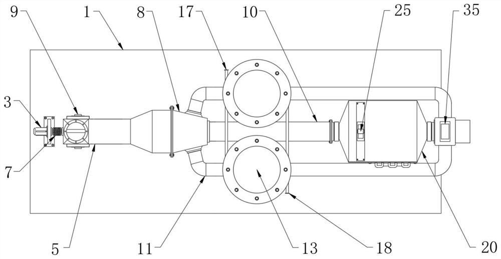
[0028] For the convenience of those skilled in the art to understand, the following in conjunction with the attached Figure 1-9 , to further specifically describe the technical solution of the present invention.

[0029]A flue gas treatment device and a flue gas waste heat recovery device for magnesium alloy processing, including a bottom plate 1, an air intake pipe 5, a heat storage tower 13 and a casing 20, and a first bracket 2 is fixed on the upper part of one end of the bottom plate 1, And one side of the first bracket 2 is equipped with a driving motor 3, and one end of the driving motor 3 runs through the first bracket 2 and is rotationally connected with the motor shaft 4; And one end of the air inlet pipe 5 is connected with the branch pipe 8; the heat storage tower 13 is installed on the upper side of the base 12, and the base 12 is fixed in the middle of the upper part of the base plate 1, and the base 12 and the heat storage tower 13 are mutually Not connected; t...


PUM


Abstract

The invention discloses a flue gas treatment device and a flue gas waste heat recovery device for processing magnesium alloys, which include a bottom plate, an air intake pipe, a heat storage tower and a casing. A first bracket is fixed on one end of the bottom plate, and a second A drive motor is installed on one side of the bracket, and one end of the drive motor runs through the first bracket and is rotationally connected with the motor shaft; the air intake pipe is fixed on the upper part of the base plate through the second support, and one end of the air intake pipe communicates with the shunt pipe The heat storage tower is installed on the upper side of the base, and the base is fixed in the middle of the upper part of the bottom plate, and the base and the heat storage tower are not connected to each other; The disassembly improves the convenience of disassembling and assembling the whole device, and improves the efficiency when the device is overhauled.

Description

technical field [0001] The invention belongs to the technical field related to flue gas treatment, and in particular relates to a flue gas treatment device and a flue gas waste heat recovery device for magnesium alloy processing. Background technique [0002] Waste heat refers to the sensible heat and latent heat contained in the products formed by energy-consuming devices during the working process of industrial production, including waste heat of high-temperature exhaust gas, waste heat of cooling medium, waste heat of waste steam and waste water, waste heat of high-temperature products and slag, chemical reactions Waste heat, combustible waste gas and waste liquid, and waste waste heat, etc., among which the recyclable waste heat resources are about 60% of the total waste heat resources. Flue gas is the most common high-temperature waste gas, and the waste heat recovery device is also the most common waste heat recovery device . [0003] However, most of the waste heat r...

Claims


Application Information

Patent Timeline
Patent Type & Authority Patents(China)
IPC IPC(8): F28D20/00F28D7/08F28F1/10F28F19/01B01D46/76F27D17/00
CPCF28D20/00F28F19/01F28D7/085F28F1/105F27D17/004F27D2017/007F28D2020/0078B01D46/76Y02E60/14Y02P10/25
Inventor 梅其民朱世龙刘明丁训华
Owner 巢湖云海镁业有限公司
Why Eureka
Try Eureka