Shearing machine for forging and pressing

A shearing machine and forging technology, which is applied in the field of forging, can solve problems such as deformation, collapse, and influence of forging size and angle of metal strip components, and achieve the effects of reducing hollowness, good fit, and good support

Inactive Publication Date: 2021-01-12
张卫明
View PDF21 Cites 0 Cited by
  • Summary
  • Abstract
  • Description
  • Claims
  • Application Information

AI Technical Summary

Problems solved by technology

[0005] Aiming at the deficiencies in the prior art, the purpose of the present invention is to provide a shearing machine for forging to solve the problem of various shapes of metal components in the prior art, including triangular metal strips, which form oblique convergence on both sides, and when shearing Due to the hollow inside, it will cause the deformation of the metal bar member with its downward hydraulic pressure, causing it to collapse inward, which will affect its forging dimension angle

Method used


Image

  • Shearing machine for forging and pressing
  • Shearing machine for forging and pressing
  • Shearing machine for forging and pressing

Examples


Embodiment 1

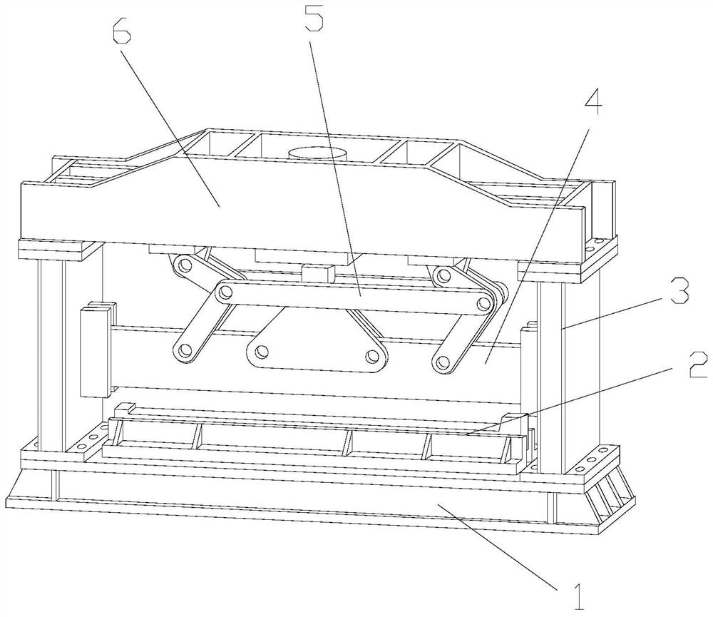
[0029] Example 1: Please refer to Figure 1-Figure 6 , the specific embodiments of the present invention are as follows:

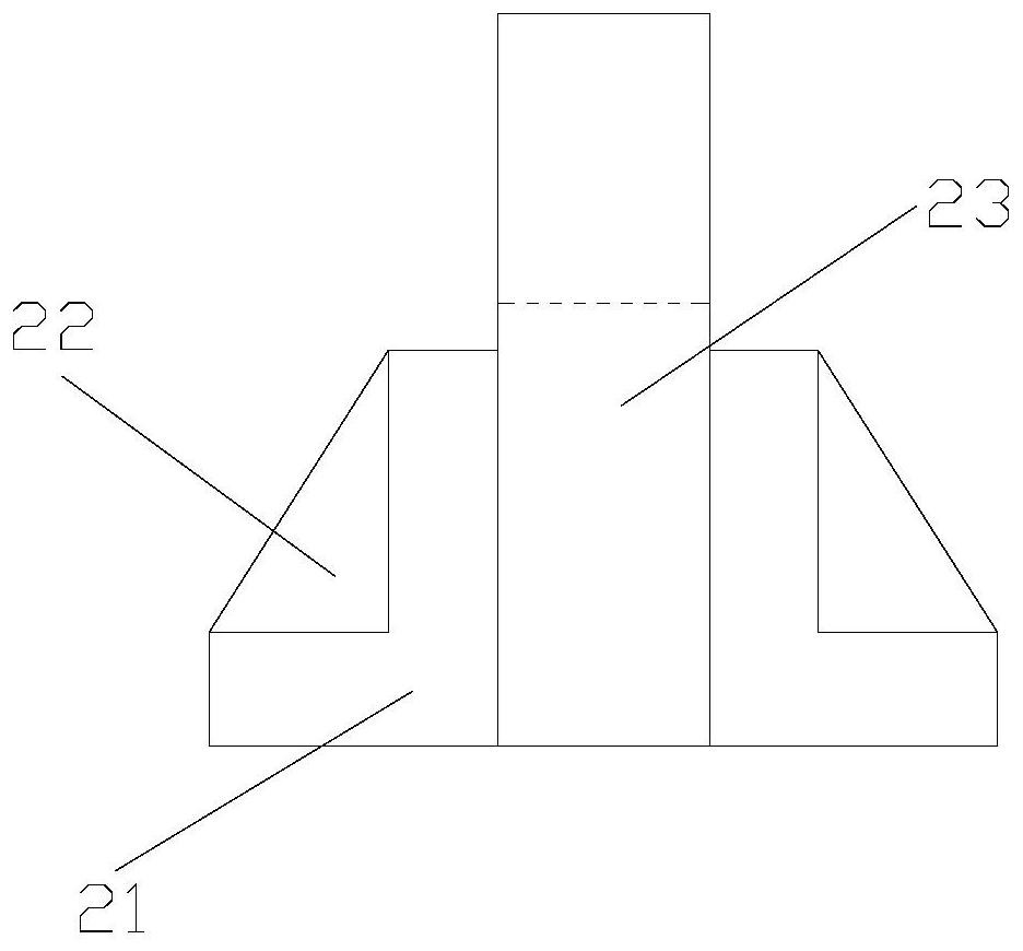
[0030] Its structure includes a base 1, a workbench 2, a support column 3, a shear knife 4, a movable frame 5, and a horizontal frame 6. The workbench 2 is horizontally installed on the upper end of the base 1 and fixed by bolts, and the support column 3 is installed vertically. On the upper end of the base 1 and on both sides of the workbench 2, the horizontal frame 6 is horizontally installed between the support columns 3 and fixed by bolts, the movable frame 5 is hinged to the lower end of the horizontal frame 6, and the shear knife 4 is movable Be connected between the support columns 3 and be hinged to the lower end of the movable frame 5; the workbench 2 includes a support base 21, a support block 22, and a deck 23, and a support block 22 is installed between the support bases 21 and welded, The card holder 23 is embedded between the supporting bloc...

Embodiment 2

[0037] Example 2: Please refer to Figure 4 , Figure 7-Figure 9 , the specific embodiments of the present invention are as follows:

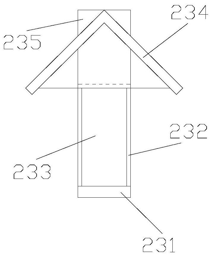
[0038] The fitting structure 234 includes a connection plate 34a, an adjustment structure 34b, an auxiliary frame 34c, and an adaptation structure 34d. The adjustment structure 34b is horizontally installed on the upper end of the connection plate 34a and fixedly connected, and the auxiliary frame 34c is vertically installed on the upper end of the connection plate 34a. And it is arranged outside the adjustment structure 34b. The adaption structure 34d is hingedly connected to the upper end of the adjustment structure 34b and abuts against the upper end of the auxiliary frame 34c.

[0039] refer to Figure 7 , the adapting structure 34d includes a top plate d1, an adapting groove d2, and a linkage structure d3, the top plates d1 are connected by a linkage structure d3 and the angle between them is less than 90 degrees, and the adapting groove...


PUM


Abstract

The invention discloses a shearing machine for forging and pressing. The shearing machine structurally comprises a base, a workbench, supporting columns, a shearing knife, a movable frame and a transverse frame, wherein the workbench is horizontally arranged at the upper end of the base; the supporting columns are vertically arranged at the upper end of the base; the transverse frame is horizontally arranged between the supporting columns; the movable frame is hinged to the lower end of the transverse frame; the shearing knife is movably connected between the supporting columns; the workbenchcomprises supporting bases, supporting blocks and a clamping base; the supporting blocks are arranged between the supporting bases; the clamping base is embedded between the supporting blocks; and theshearing knife is arranged at the upper end of the clamping base. The clamping base is arranged between the supporting bases and can be adjusted according to the included angle of a triangular metalcomponent, so that the attachment of the clamping base to the inner side of the triangular metal component is guaranteed, the hollow part of the inner side is reduced, shearing is better carried out,and collapse is prevented; and the adapting structure is arranged at the upper end of the adjusting structure, so that the adapting structure is better attached to the surface of the inner side of thetriangular metal component, good supporting is achieved, then inward collapse caused by deformation is prevented, and the forging and pressing size angle is guaranteed.

Description

technical field [0001] The invention belongs to the field of forging, and in particular relates to a shearing machine for forging. Background technique [0002] Forging is mainly used for forging and forming of metals. In the forging process, the metal will be extruded with the pressure to make it extend outward, resulting in deviations in shape, and then it is necessary to shear the metal components that have been forged to correct the metal. The leftover material of the component is sheared and formed, but the prior art has the following deficiencies: [0003] Due to the various shapes of metal components, including triangular metal strips, which form oblique convergence on both sides, when shearing, due to the hollow inside, the deformation of the metal strip will be caused by its downward hydraulic pressure, resulting in its downward The internal collapse affects its forging dimension angle. [0004] Therefore, the present application proposes a shearing machine for fo...

Claims


Application Information

Patent Timeline
IPC IPC(8): B23D15/04B23D33/02
CPCB23D15/04B23D33/02
Inventor 张卫明
Owner 张卫明
Why Eureka
Try Eureka