
Coal mine underground cable fixing traction device and operation method

A traction device and cable technology, which is applied in the installation of cables, the arrangement of cables between relatively moving parts, and electrical components, etc., can solve the problems of difficult loosening of clamps, difficult cable traction, and difficult movement of cables, etc., to achieve Easy to pull, ensure the progress of cable pulling, and facilitate the effect of cable pulling

Inactive Publication Date: 2021-01-08
文书亮
View PDF0 Cites 5 Cited by
  • Summary
  • Abstract
  • Description
  • Claims
  • Application Information

AI Technical Summary

Problems solved by technology

[0002] In the process of underground mining in coal mines, it is necessary to provide power to equipment and lighting systems, so a large number of cables need to be laid along the roadway. When laying cables, the cross-sectional area of ​​cables is large due to working environment factors. When the cable is installed, it is necessary to fix the cable through a fixing device to avoid the cable being dragged on the ground and being worn out. At present, devices such as clamps are used to fix the cable on the mine wall. However, this simple fixing device will The cable is difficult to move. After the mine is extended, it is usually necessary to pull the cable to the depth of the mine. At this time, direct pulling will easily cause sliding friction between the cable and the hoop and other metals and scratches, and the hoop is difficult to loosen, resulting in cable traction. Difficulty, for this reason we propose a coal mine underground cable fixed traction device and operation method to solve the above problems

Method used


Image

  • Coal mine underground cable fixing traction device and operation method
  • Coal mine underground cable fixing traction device and operation method
  • Coal mine underground cable fixing traction device and operation method

Examples


Embodiment Construction

[0030] The following will clearly and completely describe the technical solutions in the embodiments of the present invention with reference to the accompanying drawings in the embodiments of the present invention. Obviously, the described embodiments are only some, not all, embodiments of the present invention. Based on the embodiments of the present invention, all other embodiments obtained by persons of ordinary skill in the art without making creative efforts belong to the protection scope of the present invention.

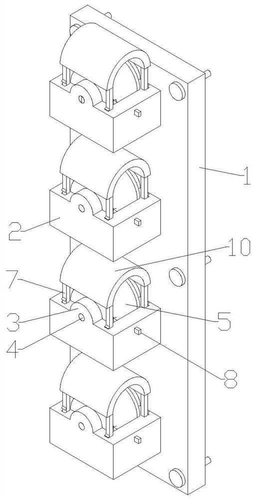
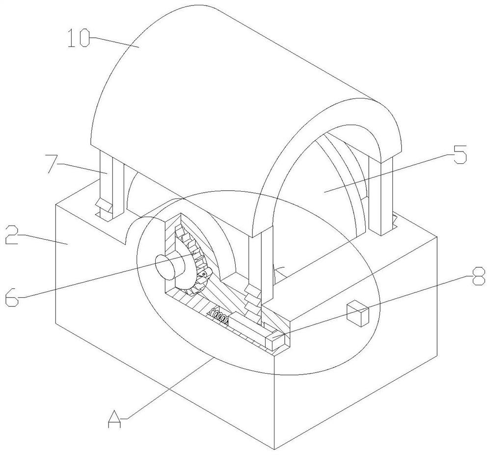
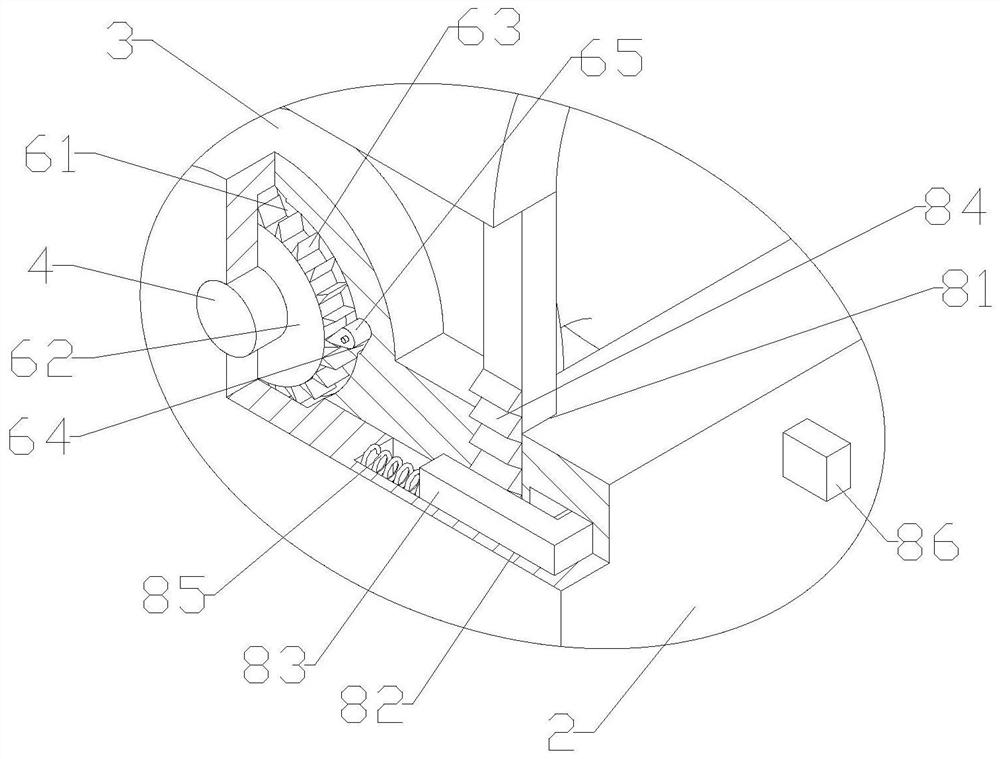
[0031] see Figure 1-4 , the present invention provides a technical solution: a coal mine underground cable fixed traction device, including a fixed plate 1 and an installation block 2, the edge of the fixed plate 1 is bolted to the mine wall by a plurality of bolts, and a plurality of installation blocks 2 are closely fitted The fixed plate 1, the clamping mechanism 9 is installed between the mounting block 2 and the fixed plate 1, the turret 3 is fixedly ins...


PUM


Abstract

The invention discloses a coal mine underground cable fixing traction device and an operation method. The coal mine underground cable fixing traction device comprises a fixing plate, an installation block, a clamping mechanism installed between the installation block and the fixing plate, rotating frames installed on the two sides of the top face of the installation block, rotating shafts connected between the rotating frames in a sleeving mode, rollers connected to the rotating shafts in a sleeving mode, limiting mechanisms installed between the rotating shafts and the rotating frames, and sliding rods; the tops of the sliding rods are connected with pressing plates, and locking mechanisms are installed between the two ends of the installation block and the sliding rods. The fixing plateis fixed to the inner wall of a mine through bolts, the mounting block is clamped and fixed to the fixing plate through the clamping mechanism, sliding locking of the sliding rod is controlled throughthe locking mechanism, when the locking mechanism is unlocked, the sliding rod can slidably adjust the distance between the pressing plate and the rollers, and the distance is increased so that a cable can penetrate through and be pulled conveniently. The rollers roll to make contact with the cable through rolling friction, the cable is prevented from being scratched, the limiting mechanism enables the rollers to roll in one direction, traction is facilitated, the cable is prevented from being pulled out in different directions, and after traction is finished, the pressing plate presses the cable to be clamped and fixed.

Description

technical field [0001] The invention relates to the technical field of mine cables, in particular to an underground cable fixing and traction device in coal mines and an operation method. Background technique [0002] In the process of underground mining in coal mines, it is necessary to provide power to equipment and lighting systems, so a large number of cables need to be laid along the roadway. When laying cables, the cross-sectional area of ​​cables is large due to working environment factors. When the cable is installed, it is necessary to fix the cable through a fixing device to avoid the cable being dragged on the ground and being worn out. At present, devices such as clamps are used to fix the cable on the mine wall. However, this simple fixing device will The cable is difficult to move. After the mine is extended, it is usually necessary to pull the cable to the depth of the mine. At this time, direct pulling will easily cause sliding friction between the cable and ...

Claims


Application Information

Patent Timeline
IPC IPC(8): H02G11/00H02G3/30
CPCH02G3/30H02G11/00
Inventor 文书亮
Owner 文书亮
Learn More