
Circuit breaker

A technology of circuit breakers and elastic parts, applied in the field of circuit breakers, can solve problems such as arc restrike, poor reliability, and easy failure, and achieve the effects of reducing energy release, increasing service life, and reducing operating frequency

Pending Publication Date: 2021-01-08
CHINT LOW VOLTAGE ELECTRICAL TECH CO LTD
View PDF0 Cites 0 Cited by
  • Summary
  • Abstract
  • Description
  • Claims
  • Application Information

AI Technical Summary

Problems solved by technology

[0002] The opening speed of the circuit breaker is very fast and the mechanism of the circuit breaker is made of rigid materials, resulting in serious bouncing phenomenon when the circuit breaker is open, that is, the moving and static contacts of the circuit breaker will have a large gap when they reach the final opening position (maximum opening distance). Large rebound, the rebound amplitude can reach half of the opening distance; when the circuit breaker breaks a large current, this rebound will cause the arc not to be extinguished in time or even the arc to reignite, seriously affecting the breaking capacity of the circuit breaker
[0003] For existing low-voltage circuit breakers, especially low-voltage universal circuit breakers, the anti-rebound structure of the contacts used in them all uses inertia to form an interlock to prevent large rebounds after the moving contacts are opened. This scheme has poor reliability. , easy to fail; and the existing contact opening anti-rebound structure cannot effectively distinguish whether the circuit breaker is breaking the fault current, so that when the circuit breaker is normally opening or breaking the fault current, the anti-rebound structure will take effect, and all the energy Released inside the operating mechanism of the circuit breaker, affecting the service life of the operating mechanism

Method used


Image

  • Circuit breaker
  • Circuit breaker
  • Circuit breaker

Examples


Embodiment Construction

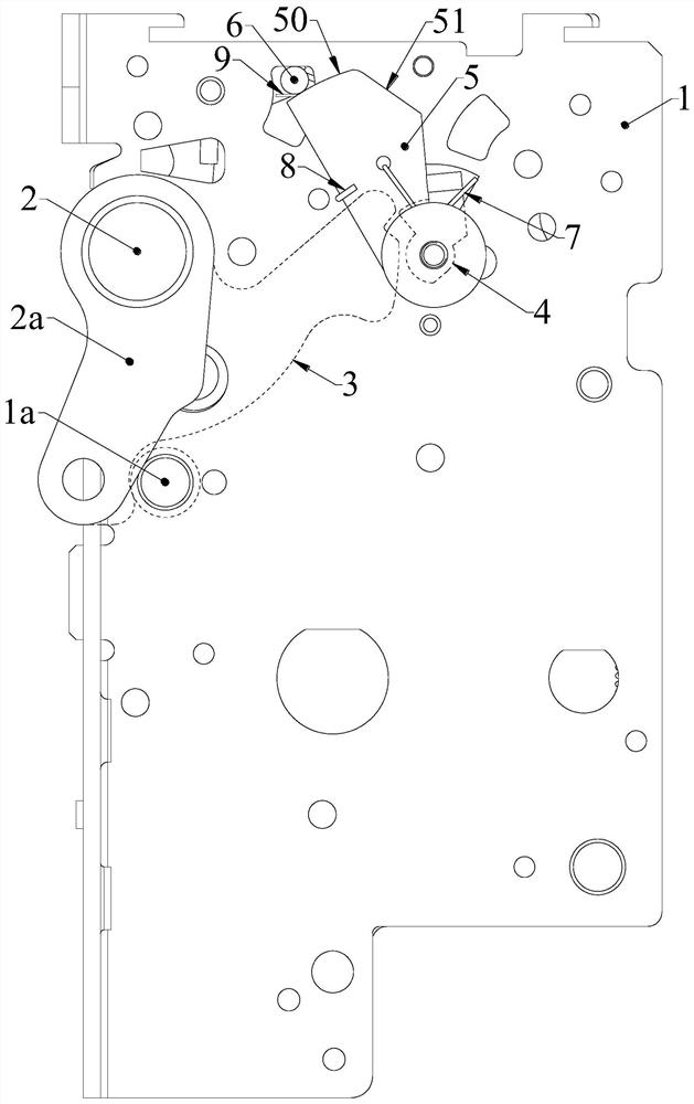
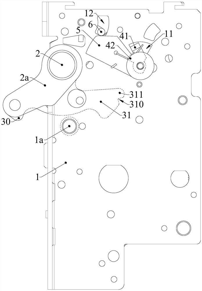
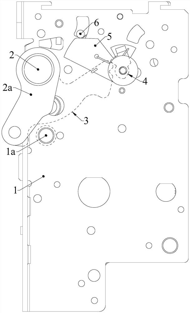
[0032] The following is attached Figure 1-10 The given examples further illustrate the specific implementation of the circuit breaker of the present invention. The circuit breaker of the present invention is not limited to the description of the following embodiments.

[0033] Such as Figure 1-6 Shown is an embodiment of the circuit breaker of the present invention.

[0034] The circuit breaker of the present invention includes a side plate assembly 1, a main shaft 2, a stop shaft 1a, a stop cantilever 3 and an opening semi-shaft 6. The side plate assembly 1 includes two side plates arranged at opposite intervals, and the two ends of the main shaft 2 are respectively Cooperating with the rotation of the two side plates, the stop cantilever 3 is arranged on the main shaft 2 to rotate synchronously with it, and the two ends of the stop shaft 1a are respectively arranged on the two side plates; the circuit breaker also includes an anti-rebound mechanism to prevent rebound Th...


PUM


Abstract

The invention relates to the field of low-voltage electric appliances, in particular to a circuit breaker. Two ends of a main shaft are respectively in running fit with two side plates of a side plateassembly, a stop cantilever is arranged on the main shaft and synchronously rotates with the main shaft, two ends of a stop shaft are respectively arranged on the two side plates, and an anti-springback mechanism comprises an anti-springback piece; when an opening half shaft rotates from an initial position to an action position to enable the circuit breaker to be opened and the opening half shaft is kept at the action position, the anti-springback piece rotates from an unlocking position to a locking position, and after the stop cantilever rotates towards the opening direction to impact thestop shaft, the stop cantilever is in limiting fit with the anti-springback piece to prevent the stop cantilever from springback towards the closing direction. When the opening half shaft rotates fromthe action position to the initial position, the opening half shaft drives the anti-springback piece to rotate from the locking position to the unlocking position, and the anti-springback piece is not in limiting fit with the stopping cantilever. According to the circuit breaker, the anti-springback mechanism is matched with the opening half shaft, so that the anti-springback mechanism takes effect only when the opening half shaft is kept at the action position.

Description

technical field [0001] The invention relates to the field of low-voltage electrical appliances, in particular to a circuit breaker. Background technique [0002] The opening speed of the circuit breaker is very fast and the mechanism of the circuit breaker is made of rigid materials, resulting in serious bouncing phenomenon when the circuit breaker is open, that is, the moving and static contacts of the circuit breaker will have a large gap when they reach the final opening position (maximum opening distance). Large rebound, the rebound amplitude can reach half of the opening distance; when the circuit breaker breaks a large current, this rebound will cause the arc not to be extinguished in time or even the arc to reignite, seriously affecting the breaking capacity of the circuit breaker. [0003] For existing low-voltage circuit breakers, especially low-voltage universal circuit breakers, the anti-rebound structure of the contacts used in them all uses inertia to form an in...

Claims


Application Information

Patent Timeline
Patent Type & Authority Applications(China)
IPC IPC(8): H01H71/12H01H1/50
CPCH01H71/121H01H1/50H01H2001/508
Inventor 辛娜秦治斌
Owner CHINT LOW VOLTAGE ELECTRICAL TECH CO LTD
Learn More