Electronic product auxiliary cooling device
A technology for cooling devices and electronic products, applied in the fields of electrical digital data processing, climate sustainability, instruments, etc., can solve the problems of unsatisfactory cooling effect and simple structure, and achieve the effect of improving cooling effect and speeding up circulation speed.
- Summary
- Abstract
- Description
- Claims
- Application Information
AI Technical Summary
Problems solved by technology
Method used
Image
Examples
Embodiment 1
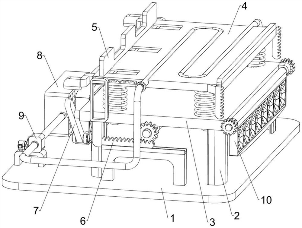
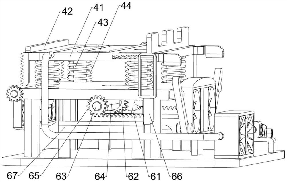
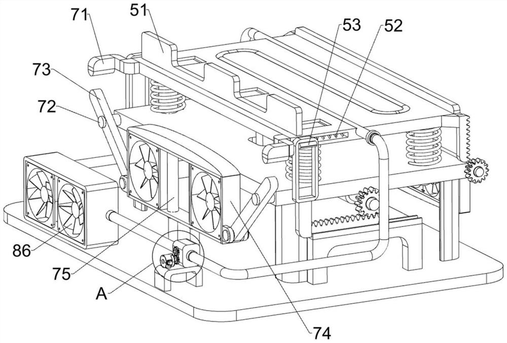
[0029] An auxiliary cooling device for electronic products, such as figure 1 , figure 2 and image 3 As shown, it includes a base plate 1, a support frame 2, a mounting plate 3, a base mechanism 4, a splint mechanism 5, a linkage mechanism 6, and a ventilation and heat dissipation mechanism 7. The left and right sides of the top of the base plate 1 are symmetrically connected with the support frame 2, four A mounting plate 3 is connected between the tops of the two support frames 2, the mounting plate 3 is provided with a base mechanism 4, the base mechanism 4 is provided with a splint mechanism 5, and a linkage mechanism 6 is provided between the splint mechanism 5 and the mounting plate 3, and the base plate 1 and the mounting plate 3 is provided with a draft cooling mechanism 7.
[0030] The base mechanism 4 includes a seat plate 41, a fixed block 42, a guide post 43 and a support spring 44. The left and right sides of the mounting plate 3 are slidingly connected with th...
Embodiment 2
[0036] On the basis of Example 1, such as image 3 and Figure 4As shown, a water-cooling mechanism 8 is also included, and the water-cooling mechanism 8 includes a copper pipe 81, a high temperature resistant water pipe 82, a one-way valve 83, a mounting frame 84, a heat dissipation pipe 85 and a heat dissipation fan 86, and a copper pipe is connected in the middle of the top of the seat plate 41. 81, the front end of copper pipe 81 is connected with check valve 83, the upper end of check valve 83 and the rear end of copper pipe 81 are all connected with high temperature resistant water pipe 82, the left rear side of bottom plate 1 top is connected with mounting bracket 84, the tail of high temperature resistant water pipe 82 End is connected with mounting frame 84, and multiple cooling pipes 85 are connected in mounting frame 84, and two cooling fans 86 are connected in mounting frame 84, and cooling fan 86 is positioned at the left side of cooling pipe 85.
[0037] Cold wa...
Embodiment 3
[0039] On the basis of Example 2, such as figure 1 , Figure 5 and Figure 6 As shown, a circulation pump mechanism 9 is also included, and the circulation pump mechanism 9 includes a micromotor 91, a casing 92, a fan plate 93 and an opposing gear set 94, a micromotor 91 is installed on the left front side of the bottom plate 1, and a high temperature resistant water pipe on the front side 82 is connected with casing 92, and the casing 92 is rotatably connected with two fan plates 93, and the lower fan plate 93 left end is connected with the output shaft of micromotor 91, and is connected with opposing gear set 94 between the two fan plates 93.
[0040] The micromotor 91 can be started to rotate, and the rotation of the micromotor 91 can drive the fan plate 93 on the lower side to rotate, and the fan plate 93 on the upper side can be driven to rotate by the opposite gear set 94, and the rotation of the fan plate 93 can accelerate the flow rate of water, thereby enabling To f...
PUM
 Abstract
Description
Claims
Application Information
 - R&D
- Intellectual Property
- Life Sciences
- Materials
- Tech Scout
- Unparalleled Data Quality
- Higher Quality Content
- 60% Fewer Hallucinations
Browse by: Latest US Patents, China's latest patents, Technical Efficacy Thesaurus, Application Domain, Technology Topic, Popular Technical Reports.
© 2025 PatSnap. All rights reserved.Legal|Privacy policy|Modern Slavery Act Transparency Statement|Sitemap|About US| Contact US: help@patsnap.com


