
Welding equipment convenient to disassemble and used for vibrating disk body production

A technology of welding equipment and vibrating plate, which is applied in the direction of welding equipment, auxiliary welding equipment, welding/cutting auxiliary equipment, etc. It can solve the problems of inability to ensure the uniformity of butt joints, inability to vibrate and screen materials, and poor material conveying effect, etc., to achieve compactness Good performance, reduce difficulty and ensure the effect of uniformity

Active Publication Date: 2021-01-08
萍乡市铛铛自动化科技有限公司
View PDF5 Cites 0 Cited by
  • Summary
  • Abstract
  • Description
  • Claims
  • Application Information

AI Technical Summary

Problems solved by technology

[0004] The purpose of the present invention is: in order to solve the problem that the existing welding equipment has a poor support effect on the welding position of the vibration plate during the welding process of the vibration plate, so that the regularity of the butt joint cannot be guaranteed, and its The use effect in the later period, and the existing vibrating plate is generally only one plate surface, so that the cover vibrating plate can only play the role of vibrating conveying, and cannot vibrate and screen the material, so that the conveying effect of the material is poor , reduces the problem of utilization rate, and provides a welding equipment for the production of the vibrating plate body that is easy to disassemble

Method used

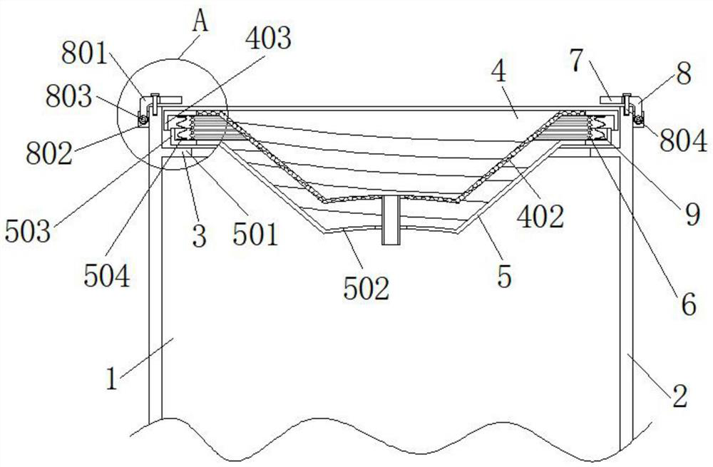
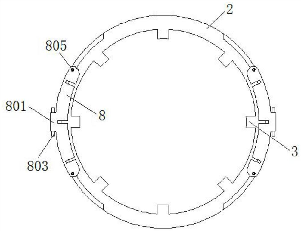
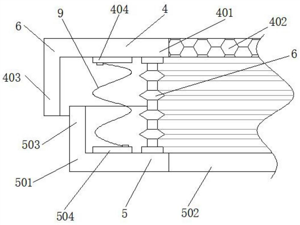

Image

  • Welding equipment convenient to disassemble and used for vibrating disk body production
  • Welding equipment convenient to disassemble and used for vibrating disk body production
  • Welding equipment convenient to disassemble and used for vibrating disk body production

Examples


Embodiment Construction

[0024] The following will clearly and completely describe the technical solutions in the embodiments of the present invention with reference to the accompanying drawings in the embodiments of the present invention. Obviously, the described embodiments are only some, not all, embodiments of the present invention. Based on the embodiments of the present invention, all other embodiments obtained by persons of ordinary skill in the art without making creative efforts belong to the protection scope of the present invention.

[0025] In the description of the present invention, it should be noted that the terms "center", "upper", "lower", "left", "right", "vertical", "horizontal", "inner", "outer" etc. The indicated orientation or positional relationship is based on the orientation or positional relationship shown in the drawings, and is only for the convenience of describing the present invention and simplifying the description, rather than indicating or implying that the referred d...


PUM


Abstract

The invention discloses welding equipment convenient to disassemble and used for vibrating disk body production, and belongs to the technical field of vibrating disk machining. The welding equipment comprises an equipment main body. A fixed frame is arranged on the outer side of the equipment main body. The four corners of the inner top end of the fixed frame are provided with limit plates. A second filtering assembly is arranged on the tops of the limiting plates. A rubber cushion is arranged at the top of the second filtering assembly. Multiple sets of elastic pieces are uniformly arranged on the outer side of the rubber cushion. A first filtering assembly is arranged on the top of the rubber cushion. According to the welding equipment, by arranging a vibrating groove and a filtering net, when the equipment main body conducts spiral vibrating discharging on materials, part of the materials are subjected to vibrating screening through the filtering net, the screened materials fall into the vibrating groove and are subjected to rolling discharging along the inner wall of the vibrating groove, and therefore the materials can be screened while discharging is conducted, the material conveying effect of the welding equipment is better, and the usage rate is increased.

Description

technical field [0001] The invention relates to the technical field of vibration plate processing, in particular to a welding device for the production of a vibration plate body that is easy to disassemble. Background technique [0002] The vibrating plate is an auxiliary feeding device for automatic assembly or automatic processing machinery, referred to as the part feeding device for short. The working principle of the vibrating plate: the frequency converter, the motor, and the automatic conveying function, and during the processing of the vibrating plate, some docking parts need to be used It is fixed by welding, and corresponding welding equipment has appeared. [0003] However, in the process of welding the vibration plate, the existing welding equipment has a poor support effect on the welding position of the vibration plate, so that the uniformity of the butt joint cannot be guaranteed, and the later use effect is reduced to a certain extent. Some vibrating discs ge...

Claims


Application Information

Patent Timeline
IPC IPC(8): B23K37/04B23K37/00
CPCB23K37/0435B23K37/00
Inventor 贺晓钢周锴
Owner 萍乡市铛铛自动化科技有限公司
Learn More