Spinning device and forming method for laser assisted shearing

A laser-assisted, spinning forming technology, applied in feeding devices, positioning devices, storage devices, etc., can solve the problems of no laser heat source irradiation, lack of precise position control parameters, etc., to avoid serious work hardening, and is conducive to engineering. Application, the effect of improving the forming ability

Active Publication Date: 2021-10-15
SHANGHAI JIAOTONG UNIV
View PDF9 Cites 0 Cited by
  • Summary
  • Abstract
  • Description
  • Claims
  • Application Information

AI Technical Summary

Problems solved by technology

However, there are obvious deficiencies in the existing laser spinning process: the laser heat source does not irradiate the maximum tensile deformation zone, and there is a lack of precise position control parameters

Method used


Image

  • Spinning device and forming method for laser assisted shearing
  • Spinning device and forming method for laser assisted shearing
  • Spinning device and forming method for laser assisted shearing

Examples


Embodiment 1

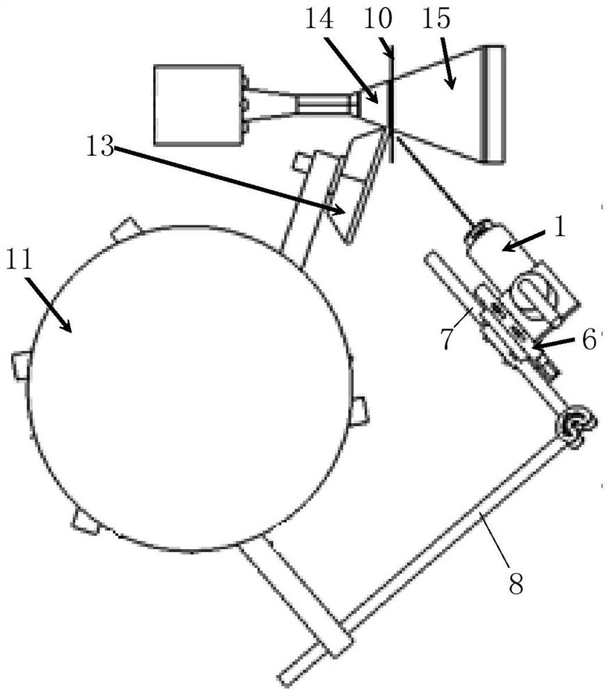
[0091] The invention provides a spinning device for laser-assisted shearing, including a spinning assembly and a laser adjustment assembly, the laser adjustment assembly includes a laser 1, and the laser 1 is installed on the spinning assembly through an adjustable connection assembly, wherein , the laser 1 is used to irradiate the workpiece and can correct the irradiation position of the laser 1 on the workpiece through an adjustable connection assembly, and the spinning assembly is used for spinning the workpiece 10 .

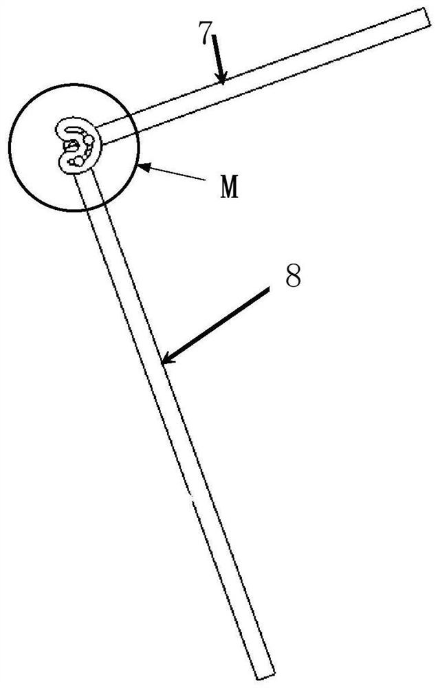
[0092] Specifically, the spinning assembly includes a support frame, the adjustable connection assembly includes a connecting rod structure and a moving assembly, one end of the connecting rod structure is installed on the supporting frame, and the moving assembly is connected to the other end of the connecting rod structure , the laser 1 is installed on the mobile assembly. The two connecting rods of the connecting rod structure, the first connecting rod 7 a...

Embodiment 2

[0110] In this embodiment, an aluminum alloy cylinder with a half taper angle of 20° and a radius of the small end of 20mm is selected as the finished product. The workpiece 10 is a 2024 aluminum alloy circular blank with a radius of 100mm and a thickness of 2mm. Laser-assisted shearing and spinning, the fillet radius r of the rotary wheel 13 is 5 mm.

[0111] Step S1: Spinning process parameter design, according to 2024 aluminum alloy, select the feed rate f as 1㎜ / r, and determine the radius R of the blank laser irradiation spot 18 according to the feed rate f and the radius of the round corner of the rotary wheel 13 5㎜ j It is 2.5㎜; according to the diameter of the small end of the 2024 aluminum alloy product, the constant linear velocity V of the mandrel for shearing and spinning is determined to be 100㎜ / s; according to the aluminum alloy material, the forming temperature is 300°C, and the YLR produced by the matching IPG company is used -1500 single-mode resonant laser tra...


PUM


Abstract

The invention provides a laser-assisted shearing spinning device and forming method, including a spinning assembly and a laser adjustment assembly, the laser adjustment assembly includes a laser, and the laser is installed on the spinning assembly through an adjustable connection assembly, The laser is used to irradiate the workpiece and can correct the irradiation position of the laser on the workpiece through the adjustable connection assembly. The spinning assembly is used to spin the workpiece. The structure design of the invention is refined, and the laser heat source is precise. Input, multi-pass or one-pass process can be used to realize the spinning processing of the small half-cone angle cylinder, which solves the problem of difficult forming of the thin-walled cylinder with small half-cone angle and is difficult to form. Compared with the existing technology, which only determines the circumferential direction of the laser heating of the sheet metal Compared with the position, through the combined precise control of the radial and circumferential positioning of the heating position of the sheet metal, the bending zone and the shearing zone can be heated at the same time, and the laser heat source can be accurately loaded to all deformation zones, achieving better forming processing effect .

Description

technical field [0001] The invention relates to the technical field of metal plate spinning forming, in particular to a laser-assisted shearing spinning device and a forming method. Background technique [0002] Lightweight alloy conical thin-walled components are a typical product widely used in aerospace vehicles. Currently, multi-pass shearing and spinning processes are used to complete the integral forming of such high-precision equal-wall-thickness thin-walled components. Due to the severe work hardening of materials caused by multi-pass cold shear spinning, the hard-to-deform light alloy materials will crack, resulting in processing failure, and the interspersed annealing process will bring long process chains, poor geometric accuracy of parts, and microstructure. Difficult to control etc. [0003] Shear spinning is to apply a force load to a certain point on the sheet through the rotary wheel, and the sheet has a strong plastic flow in a small local area, and the thi...

Claims


Application Information

Patent Timeline
Patent Type & Authority Patents(China)
IPC IPC(8): B21D22/16B21D43/28B21D37/16
CPCB21D22/16B21D37/16B21D43/287
Inventor 于忠奇王凤琪周宇
Owner SHANGHAI JIAOTONG UNIV
Why Eureka
Try Eureka