
Load switch

A technology of load switches and components, applied in the direction of electric switches, power devices inside switches, electrical components, etc., can solve problems such as long operating time, contact vibration, burning, etc., and achieve the effect of high intelligence and improved reliability

Pending Publication Date: 2021-01-05
BEIJING JINGREN ELECTRICAL CO LTD
View PDF10 Cites 2 Cited by
  • Summary
  • Abstract
  • Description
  • Claims
  • Application Information

AI Technical Summary

Problems solved by technology

This kind of load switch adopts a gear reduction mechanism. The gear pushes the moving reed to go through the entire contact gap process at a nearly uniform speed. Under the action of the action of the crown gear, the teeth of the crown gear mesh with the front gear again, and the resulting vibration causes the risk of vibration during the closing process of the contacts. In addition, the arcing generated when the distance between the dynamic and static contacts is small is very easy to cause the The contact is burnt, which seriously endangers the safety of the load switch

Method used


Image

  • Load switch
  • Load switch
  • Load switch

Examples


no. 1 example

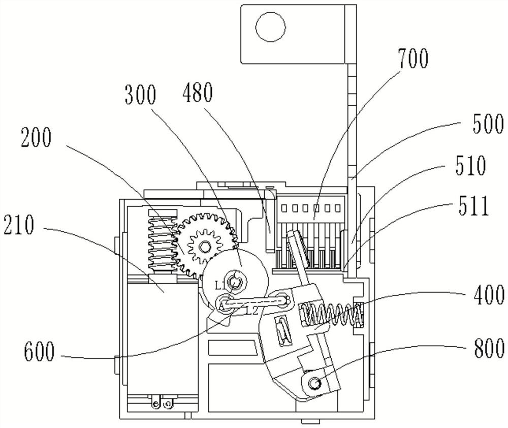
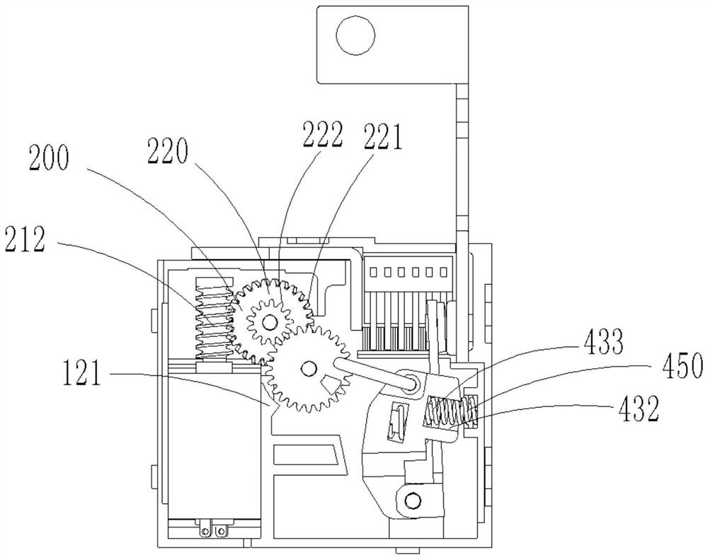
[0044] Such as Figure 1 to Figure 10 As shown, this embodiment discloses a load switch, the load switch includes a motor-driven reduction gear assembly 200, a moving contact assembly 400, and an operation that is rotationally connected to the motor-driven reduction gear assembly 200 and the moving contact assembly 400 respectively. Assembly 300 , static contact assembly 500 , at least one connecting rod 600 connecting the operating assembly 300 and the moving contact assembly 400 , and an arc extinguishing device 700 .

[0045] Wherein, the moving contact assembly 400 can rotate around the shaft 800, when the motor drives the reduction gear assembly 200 to drive the moving contact assembly 400 to rotate through the operating assembly 300 and the connecting rod 600, the The movable contact 420 on the movable contact assembly 400 is connected or disconnected from the static contact assembly 500, respectively as figure 2 and figure 1 shown.

[0046] The load switch of the pr...

no. 2 example

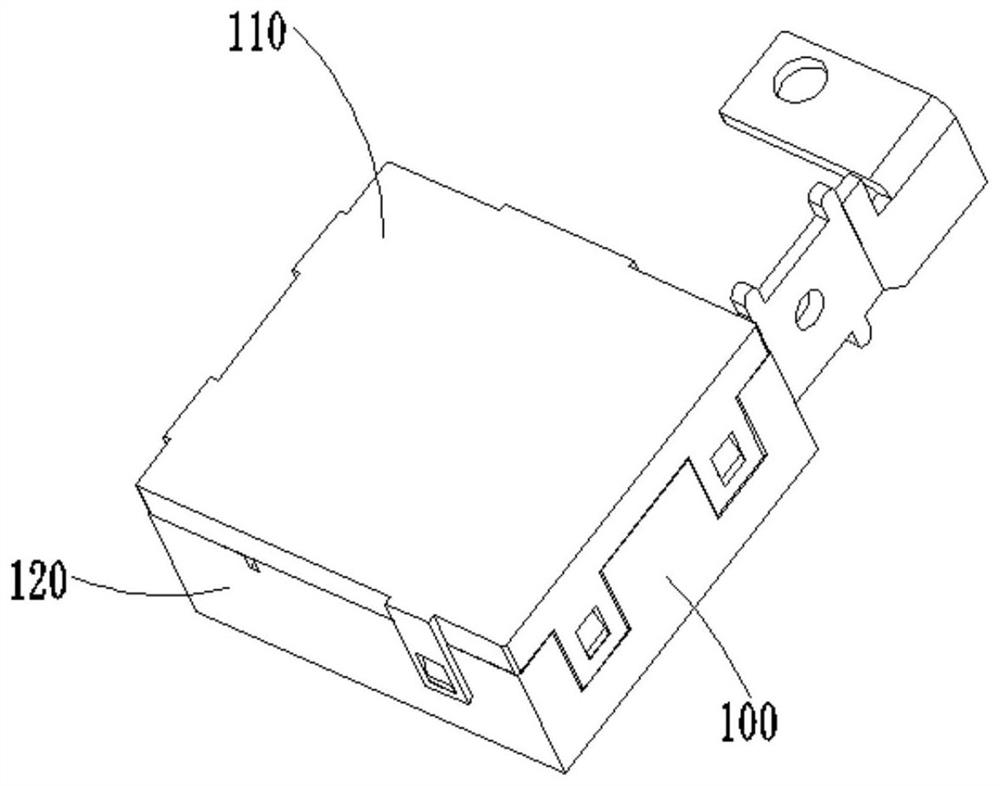
[0065] In this embodiment, the load switch can also be realized in other ways, such as Figure 9 and Figure 10 shown. In this embodiment, the shaft 800 passes through the moving contact rod 410, and the two ends of the shaft 800 are respectively fixed on the upper cover 110 and the lower cover 120 of the insulating housing 100, the moving contact The head rod 410 can rotate around the shaft 800, and the two ends of the connecting rod 600 are respectively movably connected with the operation assembly 300 and the contact support 430. When the operation assembly 300 is in the motor reduction gear assembly 200 When rotating under the drive of the connecting rod 600, the contact support 430 can translate relative to the insulating shell 100, and a sliding groove 436 is provided at the bottom of the contact support 430, and the insulating shell 100 is provided with a positioning block or slide rail matched with the sliding groove 436, and the contact support 430 can translate alo...


PUM


Abstract

The invention provides a load switch. The load switch is characterized by comprising a motor-driven reduction gear assembly (200), a moving contact assembly (400), an operation assembly (300), a static contact assembly (500), at least one connecting rod (600) and an arc extinguishing device, wherein the operation assembly (300) and the static contact assembly (500) are rotatably connected with themotor-driven reduction gear assembly (200) and the moving contact assembly (400) respectively; the moving contact assembly (400) can rotate around a shaft (800), and when the motor drives the reduction gear assembly (200) to drive the moving contact assembly (400) to rotate through the operation assembly (300) and the connecting rod (600), a moving contact (420) on the moving contact assembly (400) is connected with or disconnected from the static contact assembly (500).According to the invention, rapid and reliable contact of the switch contact can be realized, and contact burnout and melting caused by arc discharge are avoided.

Description

technical field [0001] The invention relates to the technical field of low-voltage electrical appliances, in particular to a load switch. Background technique [0002] The prior art (patent number: 201610674268.2) discloses a technology of a motor relay that can realize rapid contact closure. It is a built-in load switch used in a smart meter, and its contact system is contacted in the form of a reed. The opening distance is mostly 2mm-3mm. The problem with this contact form is that the current-carrying area of ​​the moving shrapnel is small, which affects the temperature rise of the product; the opening distance is small, and the arc breaking capability is extremely limited. For smart meters that need to switch 80A or even larger loads, the arc breaking capability of this contact system will directly affect the reliability of smart meters. [0003] The prior art (patent number: 201720803291.7) discloses a motor-type stable relay technology, which uses a motor-driven gear r...

Claims


Application Information

Patent Timeline
IPC IPC(8): H01H3/26H01H3/32H01H3/40H01H9/34
CPCH01H3/26H01H3/32H01H3/40H01H9/34
Inventor 邓艺军李军挺梁光越代朔南寅
Owner BEIJING JINGREN ELECTRICAL CO LTD
Learn More