Moving auxiliary device for mounting electromechanical equipment

A technology for mobile assistance and electromechanical equipment, applied in the field of electromechanical equipment mobile auxiliary devices, can solve the problems of electromechanical equipment damage, height adjustment, heavy quality, etc., and achieve the effects of convenient movement, stable horizontal direction, and reduced extrusion deformation

Inactive Publication Date: 2021-01-05
广州鼎奥科技有限公司
View PDF6 Cites 2 Cited by
  • Summary
  • Abstract
  • Description
  • Claims
  • Application Information

AI Technical Summary

Problems solved by technology

[0002] There are generally many kinds of electromechanical equipment in the computer room, and these electromechanical equipment need to be arranged reasonably, which makes the electromechanical installation work more and more arduous. It is difficult to carry or push, which greatly reduces the work efficiency of the installers. In addition, the electromechanical equipment may fall over during the moving process, which will cause damage to the electromechanical equipment, so it needs to be improved.
[0003] At present, the electromechanical equipment is installed at different heights, and the height needs to be adjusted. At present, the height of the electromechanical equipment cannot be adjusted, and the vibration generated during the working process of the device cannot be solved in the existing device. Therefore, we propose a method for the installation of electromechanical equipment. mobility aids

Method used


Image

  • Moving auxiliary device for mounting electromechanical equipment
  • Moving auxiliary device for mounting electromechanical equipment
  • Moving auxiliary device for mounting electromechanical equipment

Examples


Embodiment Construction

[0046] The following will clearly and completely describe the technical solutions in the embodiments of the present invention with reference to the accompanying drawings in the embodiments of the present invention. Obviously, the described embodiments are only some, not all, embodiments of the present invention.

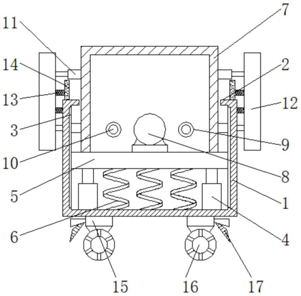
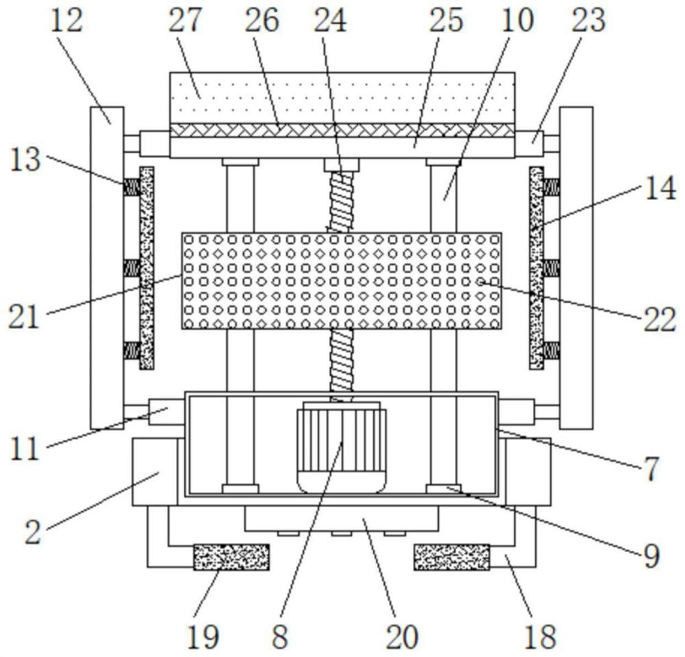
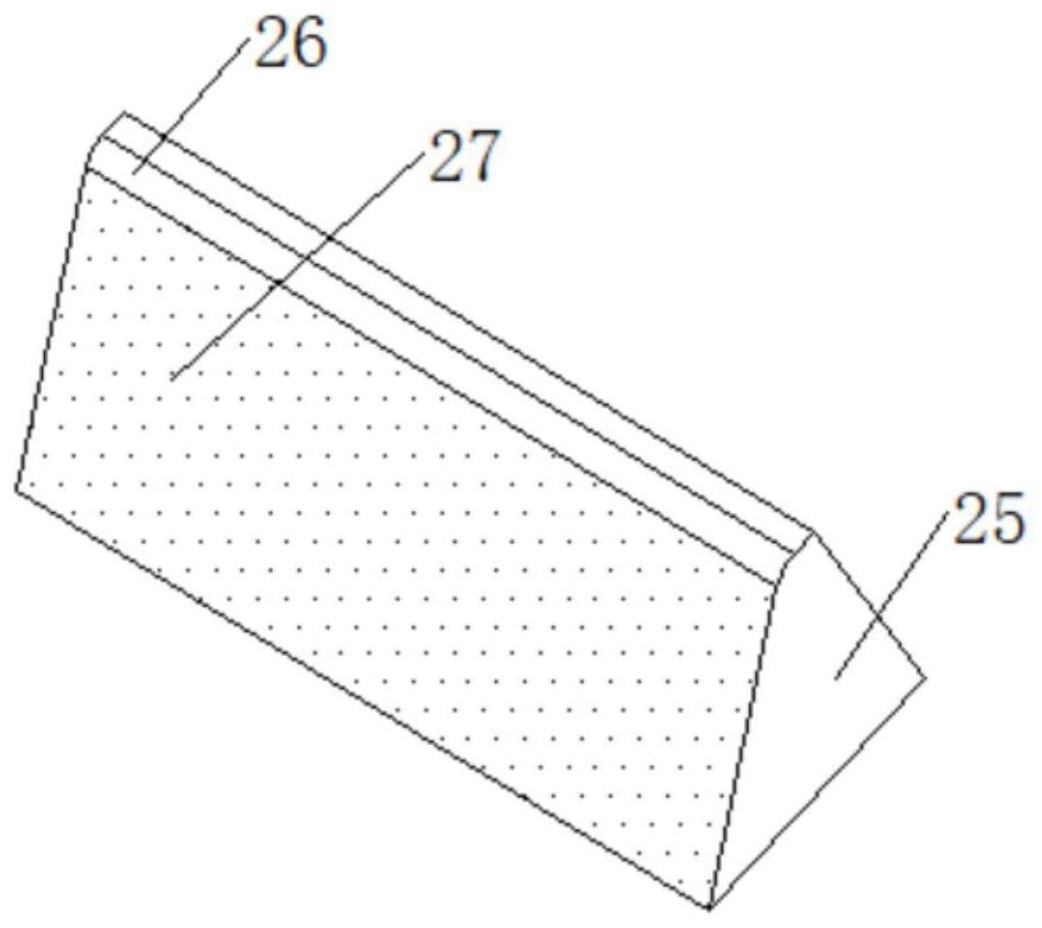
[0047] see Figure 1 to Figure 5 , the present invention provides a technical solution: a mobile auxiliary device for the installation of electromechanical equipment, including a base 1, the two sides of the top of the base 1 are provided with extension plates 2, the setting of the extension plates 2 makes the mobile plate 5 on the base 1 When the two sides move, it is ensured that the moving plate 5 will not move to the outside of the base 1. There are chute 3 on both sides of the inner cavity of the base 1. The setting of the chute 3 ensures that the moving plate 5 can move up and down inside the base 1. Movement, the middle of the two chutes 3 is slidingly connect...


PUM


Abstract

The invention discloses a moving auxiliary device for mounting electromechanical equipment, and relates to the technical field of electromechanical equipment movement auxiliary devices, in particularto the moving auxiliary device for mounting the electromechanical equipment. The moving auxiliary device comprises a base. Extension plates are arranged on the two sides of the top of the base. Sliding grooves are formed in the two sides of an inner cavity of the base. A moving plate is slidably connected to the middles of the two sliding grooves. Hydraulic rods located on the upper surface of theinner cavity of the base are fixedly mounted on the two sides of the bottom of the moving plate. According to the moving auxiliary device for mounting the electromechanical equipment, a contact plateis compressed by compression springs which are fixedly mounted on one side of the compression plate and are uniformly distributed, during passing through, when the contact plate is in contact with the two sides of the electromechanical equipment, the compression springs deform, so that the problem that the moving auxiliary device extrudes and deforms the electromechanical equipment is effectivelyreduced, and by means of the design, the two sides of the moving auxiliary device can effectively clamp the electromechanical equipment.

Description

technical field [0001] The invention relates to the technical field of mobile auxiliary devices for electromechanical equipment, in particular to a mobile auxiliary device for installing electromechanical equipment. Background technique [0002] There are generally many kinds of electromechanical equipment in the computer room, and these electromechanical equipment need to be arranged reasonably, which makes the electromechanical installation work more and more arduous. It is difficult to carry or push, which greatly reduces the work efficiency of the installers. In addition, the electromechanical equipment may fall over during the moving process, which will cause damage to the electromechanical equipment, so it needs to be improved. [0003] At present, the electromechanical equipment is installed at different heights, and the height needs to be adjusted. At present, the height of the electromechanical equipment cannot be adjusted, and the vibration generated during the wor...

Claims


Application Information

Patent Timeline
Patent Type & Authority Applications(China)
IPC IPC(8): F16M11/42F16M11/04F16F15/067G01D21/02
CPCF16F15/067F16M11/04F16M11/42G01D21/02
Inventor 古晓艳
Owner 广州鼎奥科技有限公司
Why Eureka
Try Eureka