Eureka AIR delivers breakthrough ideas for toughest innovation challenges, trusted by R&D personnel around the world.

Textile winding disc device

A coiling and workbench technology, which is applied in the textile field, can solve the problems of thread entanglement and yarn flying on the thread and affect the environment, and achieve the effects of reducing the time for installing and disassembling the coiling coil, increasing the scope of application, and maximizing benefits

Inactive Publication Date: 2021-01-05
ZHEJIANG MEILAIYA TEXTILE
View PDF11 Cites 1 Cited by
  • Summary
  • Abstract
  • Description
  • Claims
  • Application Information

AI Technical Summary

Problems solved by technology

[0004] Aiming at the deficiencies of the prior art, the present invention provides a textile winding device, which solves the problems of thread entanglement and flying wool on the thread that affect the environment during winding.

Method used

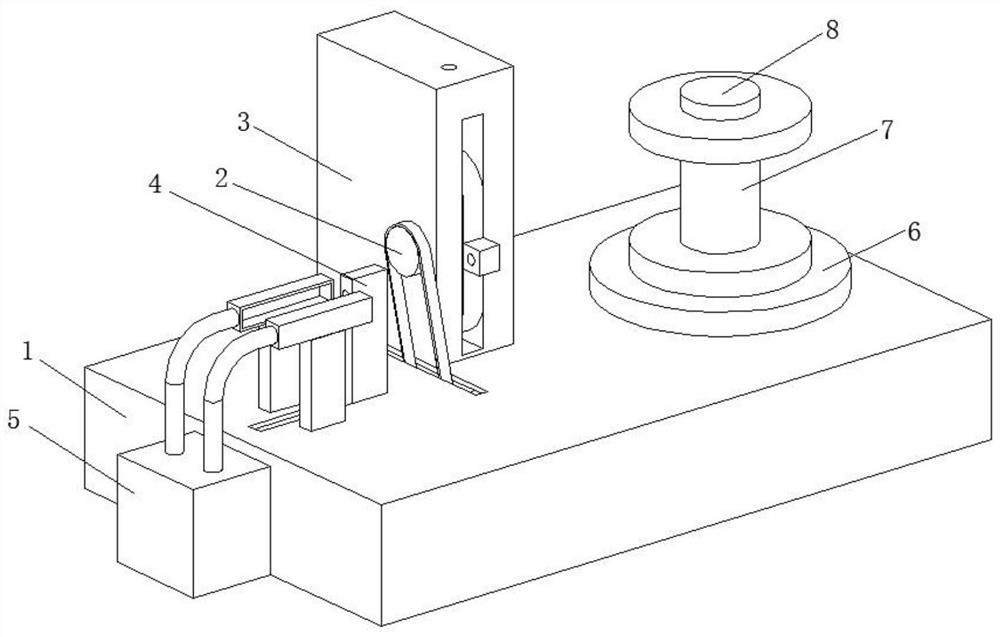
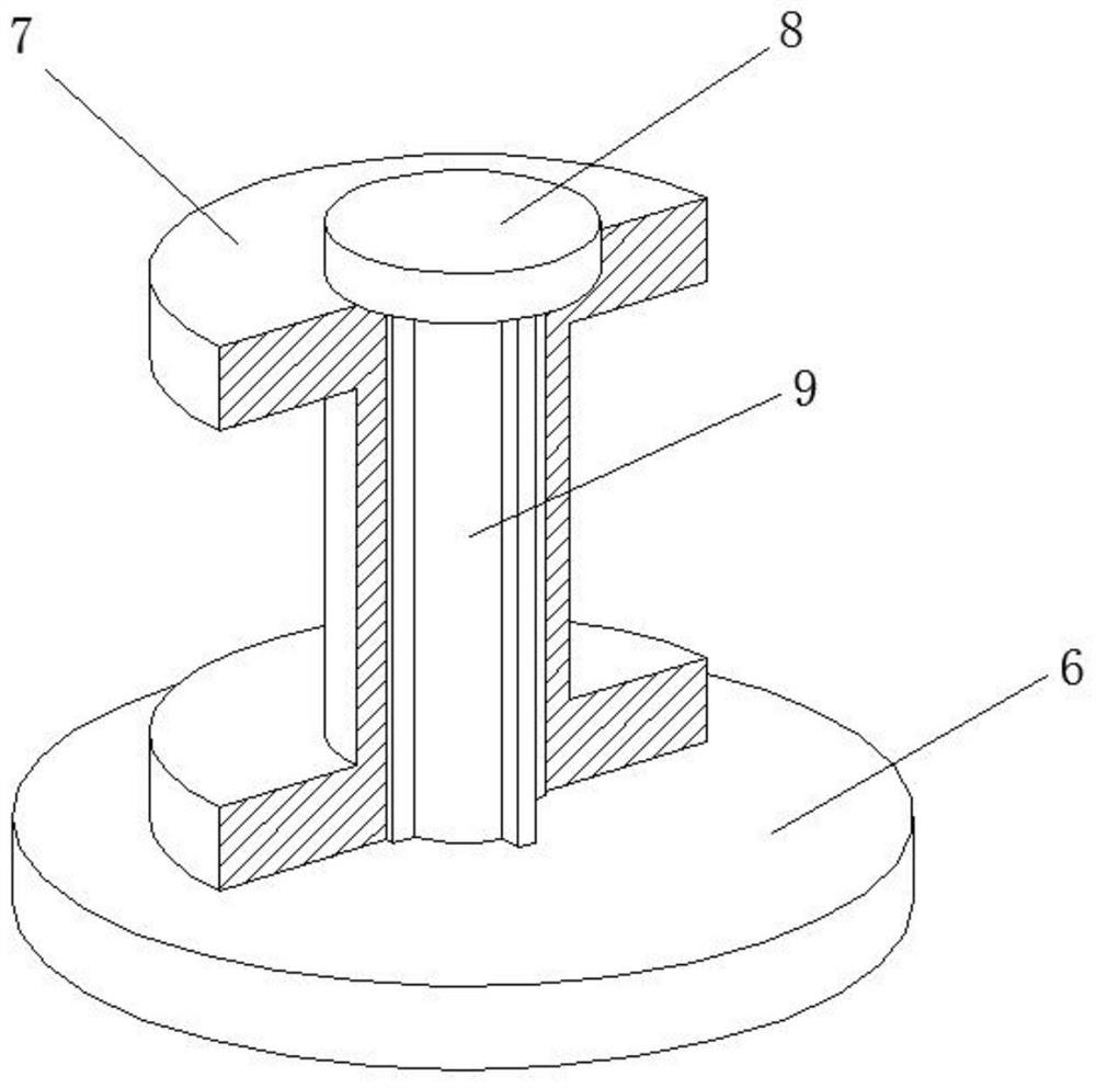
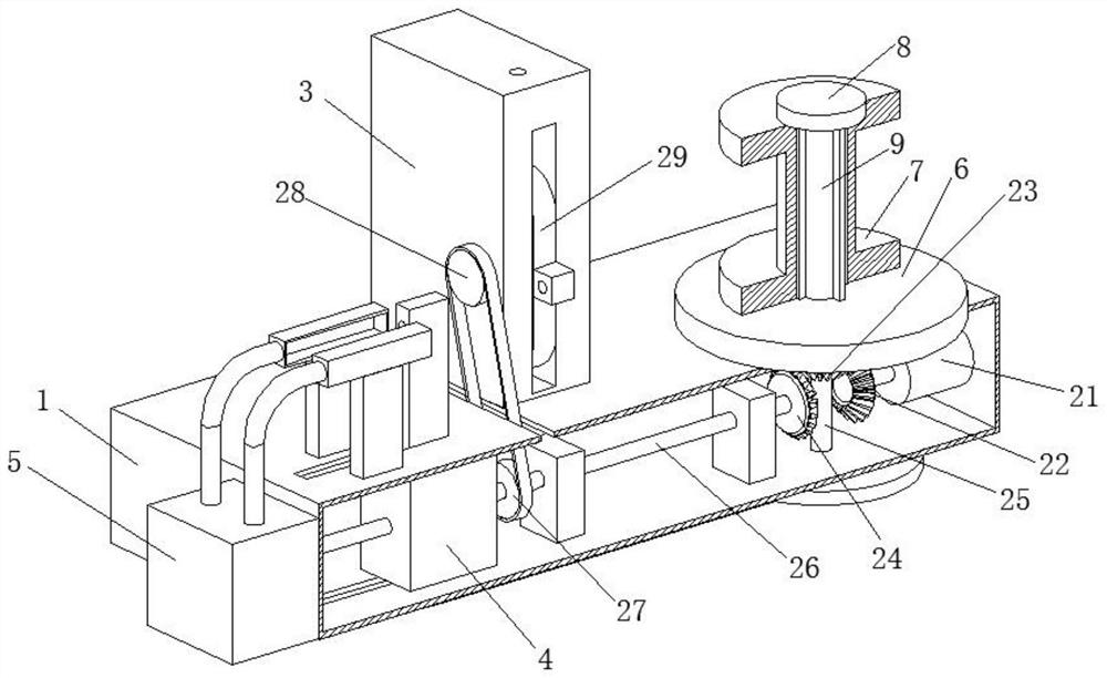

Image

  • Textile winding disc device
  • Textile winding disc device
  • Textile winding disc device

Examples


Embodiment 1

[0030]A textile winding device, such asFigure 1-Figure 5 As shown, the workbench 1 is included. The workbench 1 is provided with a transmission mechanism 2 inside, the top of the workbench 1 is welded with a fixed block 3, the inner wall of the workbench 1 is provided with a cleaning mechanism 4, and the front of the workbench 1 is provided with a collector Mechanism 5, the inner wall of the top of the workbench 1 is rotatably connected with a rotating shaft 9, the surface of the rotating shaft 9 is welded with a base 6, and the surface of the rotating shaft 9 is slidably connected with a winding reel 7, which is located above the base 6, and the top of the shaft 9 A top cover 8 is screwed.

[0031]The transmission mechanism 2 includes a motor 21. The output end of the motor 21 is clamped with a No. 1 bevel gear 22. The surface of the No. 1 bevel gear 22 is meshed with a No. 2 bevel gear 23. The surface of the No. 2 bevel gear 23 is meshed with a No. 3 bevel gear 24. A connecting shaft...

Embodiment 2

[0039]Such asFigure 6-Figure 7As shown, on the basis of Embodiment 1, in this embodiment, the fixing device 44 includes a sliding plate 441. The inner wall of the sliding plate 441 is slidably connected with a pull rod 442 and two limit posts 445, and the pull rod 442 is located in the two limit positions. Between the columns 445, the surface of the tie rod 442 is sleeved with a return spring 443, the bottom ends of the tie rod 442 and the limit column 445 are both welded with a pressure plate 444, the surface of the sliding plate 441 is slidingly connected to the inner wall of the top of the workbench 1, and the return spring 443 The two ends are in contact with the inner wall of the slide plate 441 and the upper surface of the pressure plate 444, and the pull rod 442 can drive the pressure plate 444 to move up, and then the larger diameter textile thread can be put into the slide plate 441. When you let go, the return spring 443 will The pressing plate 444 presses down the textile...


PUM


Abstract

The invention relates to the technical field of textile, and discloses a textile winding disc device. The textile winding disc device comprises a workbench, a transmission mechanism is arranged insidethe workbench, a fixing block is welded to the top of the workbench, a cleaning mechanism is arranged on the inner wall of the workbench, a collecting mechanism is arranged on the front portion of the workbench, a rotating shaft is rotatably connected to the inner wall of the top of the workbench, a base is welded to the surface of the rotating shaft, a thread reel is connected to the surface ofthe rotating shaft in a sliding mode, and a top cover is connected to the top of the rotating shaft in a threaded mode. Textile threads can be wound around the thread reel up and down repeatedly, so that the situation that the textile threads gather together and then intertwine is well prevented; and the cleaning mechanism can scrape off fine knitting wool attached to the textile threads, so thatthe knitting wool is prevented from flying everywhere and affecting the air quality in a workshop, the fine knitting wool is prevented from being inhaled by workers, and the physical health of the workers is guaranteed.

Description

Technical field[0001]The invention relates to the technical field of textiles, in particular to a textile winding device.Background technique[0002]The original intent of textile is taken from the general term of spinning and weaving, but with the continuous development and improvement of the textile knowledge system and discipline system, especially after the production of non-woven textile materials and three-dimensional composite weaving technologies, the current textile is not only traditional Hand-spinning and weaving also include non-woven fabric technology, modern three-dimensional weaving technology, modern electrostatic nano-web technology and other textiles for clothing, industrial use and decoration.[0003]At present, when the textile thread is wound on the coil, the textile thread is likely to be entangled when the coil is wound, causing the coil to be unable to continue, and there are a lot of wool on the textile thread, which may float into the air during the winding pro...

Claims


Application Information

Patent Timeline
Patent Type & Authority Applications(China)
IPC IPC(8): B65H54/54B65H54/44B65H54/30B65H54/70
CPCB65H54/54B65H54/44B65H54/30B65H54/702B65H2701/31
Inventor 阚乃亚
Owner ZHEJIANG MEILAIYA TEXTILE
Why Eureka
Eureka Blog
Learn More