
Positioning mechanism and welding fixture

A positioning mechanism and positioning structure technology, applied in welding equipment, auxiliary welding equipment, welding/cutting auxiliary equipment, etc., can solve the problem of insufficient driving force of telescopic positioning mechanism, achieve large driving force, improve positioning accuracy, and increase driving stroke Effect

Active Publication Date: 2021-01-05
ANHUI JIANGHUAI AUTOMOBILE GRP CORP LTD
View PDF7 Cites 1 Cited by
  • Summary
  • Abstract
  • Description
  • Claims
  • Application Information

AI Technical Summary

Problems solved by technology

[0003] The main purpose of the present invention is to propose a positioning mechanism and a welding fixture, aiming to solve the problem of insufficient driving force of the existing telescopic positioning mechanism due to space constraints

Method used


Image

  • Positioning mechanism and welding fixture
  • Positioning mechanism and welding fixture
  • Positioning mechanism and welding fixture

Examples


Embodiment Construction

[0044] The following will clearly and completely describe the technical solutions in the embodiments of the present invention with reference to the accompanying drawings in the embodiments of the present invention. Obviously, the described embodiments are only part of the embodiments of the present invention, not all of them. Based on the embodiments of the present invention, all other embodiments obtained by persons of ordinary skill in the art without creative efforts fall within the protection scope of the present invention.

[0045] It should be noted that if there are directional indications involved in the embodiment of the present invention, the directional indications are only used to explain the relative positional relationship, movement conditions, etc. between the components in a specific posture. If the specific posture changes , then the directional indication changes accordingly.

[0046] In addition, if there are descriptions involving "first", "second" and so o...


PUM


Abstract

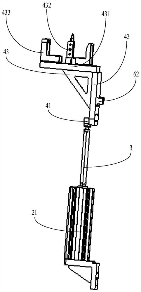
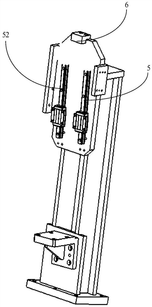
The invention discloses a positioning mechanism and a welding fixture. The positioning mechanism comprises an installation column, a linear driving structure, a lengthening rod, a positioning structure and guide structures. The installation column is arranged in the mode of extending in the first direction, the fixed end of a linear driving device is arranged on the installation column, the movable end of the linear driving device has a movement stroke in the first direction, the lengthening rod is arranged in the mode of extending in the first direction, one end of the lengthening rod is arranged at the movable end, the positioning structure is arranged at the other end of the lengthening rod, and the guide structures are arranged between the positioning structure and the installation column. The linear driving device and the positioning structure are in driving connection through the lengthening rod, the driving stroke of the linear driving structure is increased, the larger linear driving device is arranged advantageously, and therefore the larger driving force is provided; and meanwhile, the guide structures are adopted, and therefore the movable end of linear driving cannot shake after stretching out, and the positioning precision of the positioning mechanism is improved.

Description

technical field [0001] The invention relates to the technical field of automobile welding, in particular to a welding fixture of a positioning mechanism. Background technique [0002] Welding fixtures are the most important auxiliary tooling in automobile welding. Reasonable positioning and pressing of parts is the key to the design of welding fixtures. In addition to high-precision positioning of parts, the design of welding fixtures should also consider the positioning mechanism to meet the requirements of positioning space and ease of operation. , the fixed positioning method is adopted, and the parts cannot be picked up after welding. The existing telescopic positioning mechanism is generally connected to the pneumatic telescopic cylinder through a connecting block. Due to the limitation of the welding space, the telescopic cylinder can only choose a smaller model, resulting in cylinder telescopic force. If it is too small, the cylinder may be stuck after welding and ca...

Claims


Application Information

Patent Timeline
Patent Type & Authority Applications(China)
IPC IPC(8): B23K37/04
CPCB23K37/04B23K2101/006
Inventor 王宾黄星丽于海江汪小霞
Owner ANHUI JIANGHUAI AUTOMOBILE GRP CORP LTD
Learn More