Spin riveting machine and abutting device thereof

A technology of a rotary riveting machine and an abutment surface, which is applied in the field of a rotary riveting machine and its abutment device, and can solve problems such as the push-out of the nail hole to the side of the riveting head, so as to improve space utilization, improve stability, and improve general use. sexual effect

Pending Publication Date: 2021-01-05
LUSHAN COLLEGE OF GUANGXI UNIV OF SCI & TECH
View PDF14 Cites 0 Cited by
  • Summary
  • Abstract
  • Description
  • Claims
  • Application Information

AI Technical Summary

Problems solved by technology

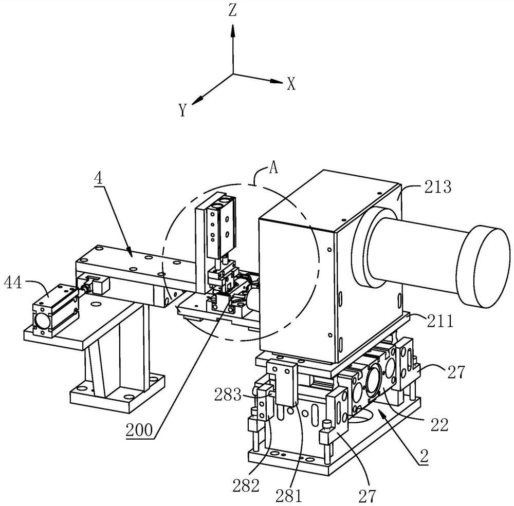
The abutment device used by the spin riveting machine in the prior art usually uses a compression cylinder to drive the compression block to move vertically to abut and compress the workpiece. However, when the abutment device is used in the horizontal direction, the When the rivet is rotated horizontally, there is a problem that the rivet head pushes the rivet from the rivet hole of the workpiece to the side of the rivet head

Method used


Image

  • Spin riveting machine and abutting device thereof
  • Spin riveting machine and abutting device thereof
  • Spin riveting machine and abutting device thereof

Examples


Embodiment Construction

[0044] The following will clearly and completely describe the technical solutions in the embodiments of the present invention with reference to the accompanying drawings in the embodiments of the present invention. Obviously, the described embodiments are only some, not all, embodiments of the present invention. Based on the embodiments of the present invention, all other embodiments obtained by persons of ordinary skill in the art without making creative efforts belong to the protection scope of the present invention.

[0045] It should be noted that when a component is said to be "fixed" to another component, it can be directly on the other component or there can also be an intervening component. When a component is said to be "connected" to another component, it may be directly connected to the other component or there may be intervening components at the same time. When a component is said to be "set on" another component, it may be set directly on the other component or t...


PUM


Abstract

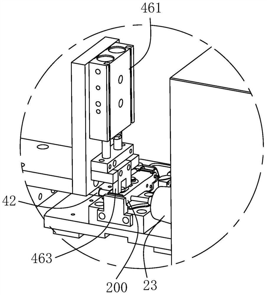
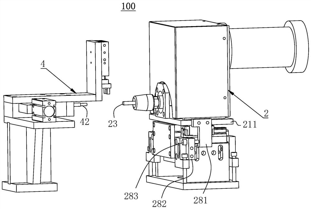
The invention provides an abutting device. The abutting device comprises a support, an abutting rod, a first locking block, a second locking block, an abutting driving piece and an abutting pressing piece. The abutting rod is arranged on the support slidably. The first locking block is arranged on the support slidably and connected with the abutting rod, and a first inclined face and a first abutting face are arranged on the first locking block. The second locking block is arranged on the support slidably, a second inclined face and a second abutting face connected with the second inclined face are arranged on the second locking block, in an initial state, the second inclined face is in sliding contact with the first inclined face, and the second abutting face and the first abutting face are spaced in parallel. The abutting driving piece is arranged on the support and connected with the second locking block. The abutting pressing piece is arranged on the support so as to abut against aworkpiece to be riveted. The workpiece can be prevented from shaking during spin riveting, and the purpose that a rivet is pushed out from one side of a rivet hole of the workpiece during spin riveting can be realized. The invention further provides a spin riveting machine with the abutting device.

Description

technical field [0001] The invention relates to the field of mechanical processing equipment, in particular to a riveting machine and an abutting device thereof. Background technique [0002] The riveting machine is an indispensable riveting equipment in the process of workpiece riveting. It relies on the principle of cold rolling to realize the riveting of the workpiece through rotation and pressure. At this stage, the riveting machine usually includes the riveting head, the cylinder or oil cylinder that drives the riveting head to move in the horizontal direction, and the motor that drives the riveting head to rotate, and most of the riveting machines use the riveting head, the cylinder body of the cylinder or the oil cylinder, and the motor. The coaxial arrangement along the horizontal direction or the coaxial arrangement of the riveting head and the motor along the horizontal direction, for example, the high-efficiency double riveting head horizontal hydraulic riveting m...

Claims


Application Information

Patent Timeline
Patent Type & Authority Applications(China)
IPC IPC(8): B21J15/12B21J15/42B21J15/30
CPCB21J15/12B21J15/42B21J15/30
Inventor 黄艳林伟健赖玉活龙裕嘉张树林许煊煚
Owner LUSHAN COLLEGE OF GUANGXI UNIV OF SCI & TECH
Why Eureka
Try Eureka