
Suction catheter

A technology for suction catheters and suction parts, applied in the direction of catheters, balloon catheters, suction devices, etc., can solve the problems of affecting myocardial blood supply and poor suction effect of thrombus, so as to improve suction efficiency, ensure normal blood supply, and delay The effect of blood flow and blood velocity

Pending Publication Date: 2021-01-05
SHENZHEN YEAPRO IND CO LTD
View PDF0 Cites 1 Cited by
  • Summary
  • Abstract
  • Description
  • Claims
  • Application Information

AI Technical Summary

Problems solved by technology

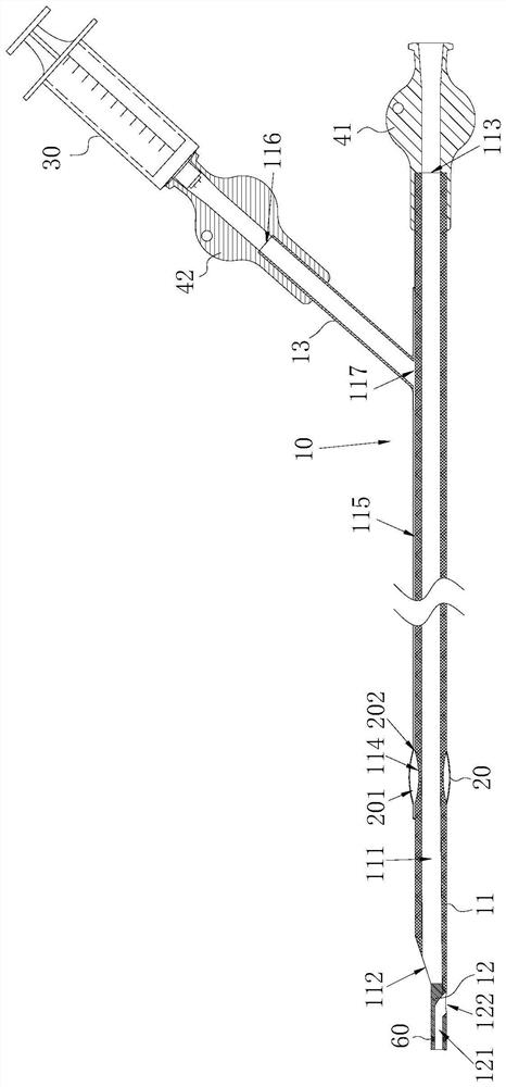
[0005] The purpose of the present invention is to provide a suction catheter, aiming to solve the technical problem in the prior art that the effect of sucking thrombus is poor when the proximal end of the blood vessel is not blocked, and the blood supply to the myocardium is affected when it is blocked.

Method used


Image

  • Suction catheter
  • Suction catheter
  • Suction catheter

Examples


Embodiment Construction

[0027] Embodiments of the present invention are described in detail below, examples of which are shown in the drawings, wherein the same or similar reference numerals designate the same or similar elements or elements having the same or similar functions throughout. The embodiments described below by referring to the figures are exemplary and are intended to explain the present invention and should not be construed as limiting the present invention.

[0028] In describing the present invention, it should be understood that the terms "length", "width", "upper", "lower", "front", "rear", "left", "right", "vertical", The orientation or positional relationship indicated by "horizontal", "top", "bottom", "inner", "outer", etc. are based on the orientation or positional relationship shown in the drawings, and are only for the convenience of describing the present invention and simplifying the description, rather than Nothing indicating or implying that a referenced device or element...


PUM


Abstract

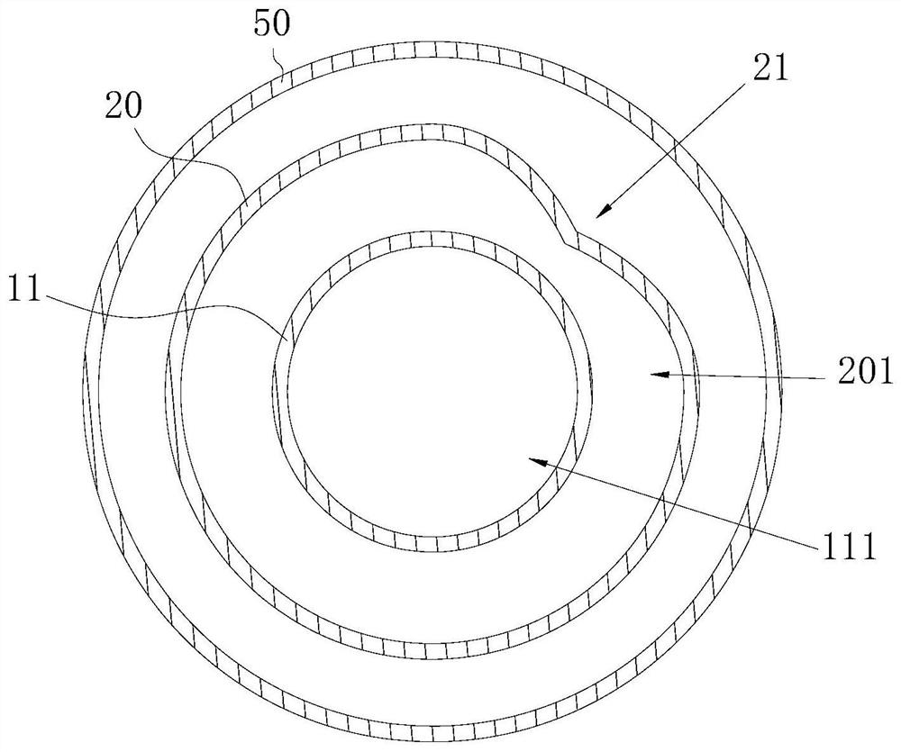
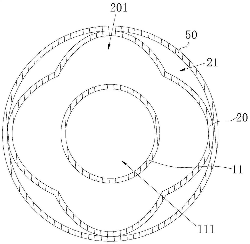
The invention provides a suction catheter. The suction catheter comprises a suction component and a balloon component, wherein the suction component is provided with a suction cavity; the balloon component is arranged on the suction component in a sleeving mode; a balloon cavity is defined by the inner wall of the balloon component and the outer wall of the suction component jointly; at least onecirculation groove extending in the extending direction of the suction component is formed in the outer wall of the balloon component; the balloon component has a contraction state when no fluid is introduced into the balloon cavity and an expansion state after the fluid is introduced into the balloon cavity through an injection port; the groove walls of the circulation grooves are distributed inthe circumferential direction of the outer wall of the balloon component at intervals; and the circulation grooves keep through from the far end to the near end when the balloon component is in the expansion state. According to the suction catheter, the circulation grooves are formed in the outer wall of the balloon component, so that when the balloon component is in the expansion state and the outer wall of the balloon component is attached to the wall of blood vessel, blood can continuously flow through the circulation grooves which are through from far to near, blood vessel blockage is prevented, normal blood supply of myocardium is guaranteed, and surgical risks are reduced.

Description

technical field [0001] The invention belongs to the technical field of medical instruments, in particular to a suction catheter. Background technique [0002] Coronary atherosclerotic heart disease has become the number one killer threatening people's health and life. Unstable coronary atherosclerotic plaque rupture will lead to the formation of acute thrombus, occlusion of the coronary artery lumen, interruption of blood flow, and ischemia or necrosis of myocardial cells in the corresponding blood supply area. The key to treating patients with acute coronary syndrome (ACS) is to quickly open the infarcted blood vessels and restore blood supply to myocardial cells, so as to reduce the size of myocardial infarction, reduce the risk of complications, and prevent possible short-term and long-term sequelae. [0003] At present, a suction catheter is usually used to aspirate the thrombus, that is, the suction catheter is sent to the thrombus site, and then the thrombus is drawn ...

Claims


Application Information

Patent Timeline
IPC IPC(8): A61M25/10A61M1/00
CPCA61M1/0023A61M25/0023A61M25/1002A61M2025/1079A61M2210/12A61M1/82A61M1/84A61M2210/005
Inventor 王平肖建平董壮
Owner SHENZHEN YEAPRO IND CO LTD
Learn More