Charging and lighting device for vacuum cleaner
A technology for lighting devices and vacuum cleaners, applied in the installation of vacuum cleaners, electrical equipment, household appliances, etc., can solve the problems of not being installed, not easy to be lost, damaged, etc., achieve good heat absorption and heat dissipation, ensure cooling effect, and improve stability. Effect
- Summary
- Abstract
- Description
- Claims
- Application Information
AI Technical Summary
Problems solved by technology
Method used
Image
Examples
Embodiment 1
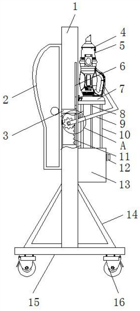
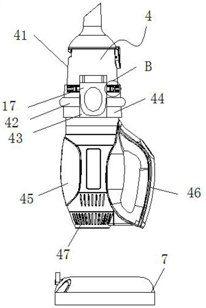
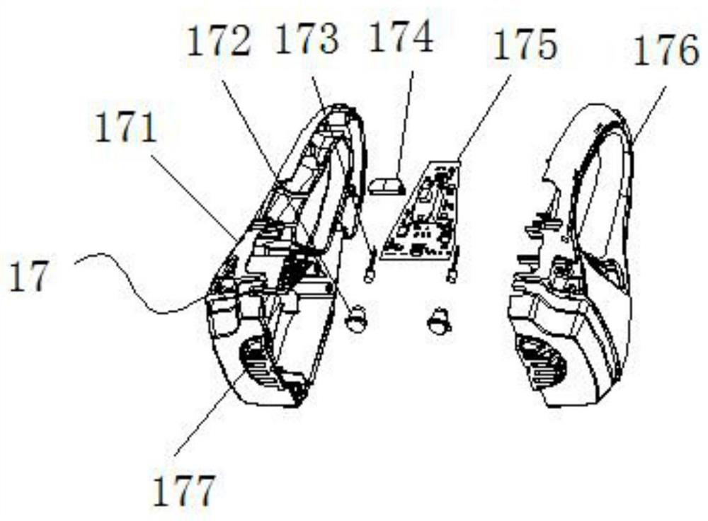
[0033] refer to Figure 1-7 , a charging and lighting device for a vacuum cleaner, comprising a mounting frame 1, a dust suction mechanism 4, a charging base 7, a stable support frame 9, a cooling liquid tank 13 and a lighting mechanism 17, and one side of the mounting frame 1 is fixed on the outer wall There is a coolant tank 13, and the inside of the installation frame 1 is installed with a driving gear 26 through the rotation of the rotating shaft, and a stable support frame 9 is fixedly installed at one end of the rotating shaft, and a drive rack 11 is slidably installed on the inner wall of the installation frame 1. The driving rack 11 and the driving gear 26 are connected through gear meshing, and the dust suction mechanism 4 is placed on the charging base 7. Due to the gravity of the dust suction mechanism 4, the driving rack 11 will be driven down automatically, and the driving rack 11 The external teeth of the drive gear 26 mesh with each other to drive the stable sup...
Embodiment 2
[0035] refer to Figure 1-7 , a charging and lighting device for a vacuum cleaner, comprising a mounting frame 1, a dust suction mechanism 4, a charging base 7, a stable support frame 9, a cooling liquid tank 13 and a lighting mechanism 17, and one side of the mounting frame 1 is fixed on the outer wall There is a coolant tank 13, and the inside of the installation frame 1 is installed with a driving gear 26 through the rotation of the rotating shaft, and a stable support frame 9 is fixedly installed at one end of the rotating shaft, and a drive rack 11 is slidably installed on the inner wall of the installation frame 1. The driving rack 11 and the driving gear 26 are connected through gear meshing, and the dust suction mechanism 4 is placed on the charging base 7. Due to the gravity of the dust suction mechanism 4, the driving rack 11 will be driven down automatically, and the driving rack 11 The external teeth of the drive gear 26 mesh with each other to drive the stable sup...
PUM
 Abstract
Description
Claims
Application Information
 - R&D Engineer
- R&D Manager
- IP Professional
- Industry Leading Data Capabilities
- Powerful AI technology
- Patent DNA Extraction
Browse by: Latest US Patents, China's latest patents, Technical Efficacy Thesaurus, Application Domain, Technology Topic, Popular Technical Reports.
© 2024 PatSnap. All rights reserved.Legal|Privacy policy|Modern Slavery Act Transparency Statement|Sitemap|About US| Contact US: help@patsnap.com


