
Image analysis method, segmentation method, bone density measurement method, learning model creation method, and image creation device

An image analysis and learning model technology, applied in the field of image generation devices, can solve problems such as complicated operations and deviations, and achieve the effect of improving detection accuracy

Pending Publication Date: 2021-01-01
SHIMADZU SEISAKUSHO CO LTD
View PDF4 Cites 0 Cited by
  • Summary
  • Abstract
  • Description
  • Claims
  • Application Information

AI Technical Summary

Problems solved by technology

In order to determine the region of the bone part, the operator has to manually determine the region in advance, which is not only complicated, but also has the problem of deviation from the region determined by the operator.

Method used


Image

  • Image analysis method, segmentation method, bone density measurement method, learning model creation method, and image creation device
  • Image analysis method, segmentation method, bone density measurement method, learning model creation method, and image creation device
  • Image analysis method, segmentation method, bone density measurement method, learning model creation method, and image creation device

Examples


Embodiment Construction

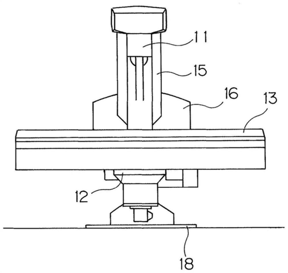
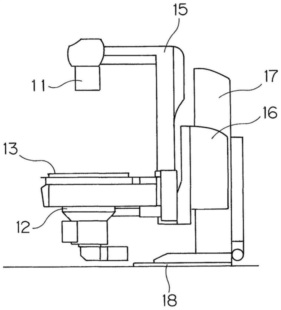
[0048] Embodiments of the present invention will be described below based on the drawings. figure 1 It is a schematic front view of a bone image generating device according to an embodiment of the present invention that also functions as an X-ray imaging device, figure 2 is its side view outline. In addition, in this embodiment, a case where the present invention is applied to a bone image generating device that generates images of bones of a subject, such as bones and organs, will be described.

[0049] The bone image generating device that also functions as an X-ray imaging device is also called an X-ray fluoroscopic imaging stand, and includes: a top plate 13; an X-ray tube holding member 15; X-ray irradiation unit 11; X-ray detection unit 12 having an X-ray detector such as a flat panel detector or an image intensifier (I.I.) arranged on the opposite side of the top plate 13 to the X-ray irradiation unit 11 .

[0050] The top plate 13, the X-ray tube holding member 15, ...


PUM


Abstract

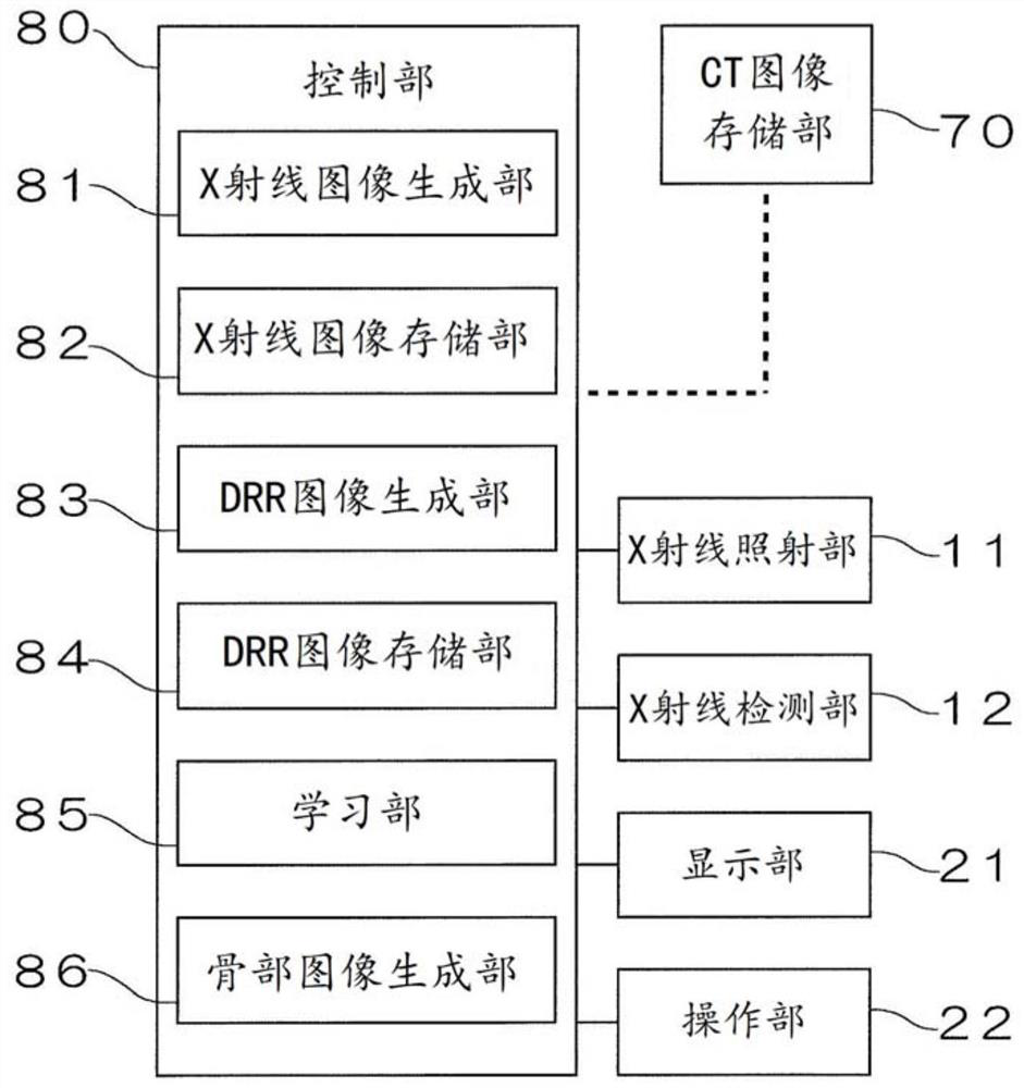
A control unit (80) comprises: an X-ray image creation unit (81); an X-ray image memory unit (82) for storing an X-ray image and an X-ray image-use training bone part image; a DRR image creation unit(83) for creating a DRR image from a region containing a bone part; a DRR image memory unit (84) for storing the DRR image and a DRR image-use training bone part image for machine learning use; a learning unit (85) which uses the X-ray image and the X-ray image-use training bone part image to perform machine learning and uses the DRR image and the DRR image-use training bone part image to performmachine learning, thereby creating a learning model for recognizing the bone part; and a bone part image creation unit (86) which uses the learned model created in the learning unit (85) to convert anX-ray image of a region containing the bone part of a subject and create an image representing the bone part.

Description

technical field [0001] The present invention relates to an image analysis method, a segmentation method, a bone density measurement method, a learning model generation method and an image generation device. Background technique [0002] In recent years, a bone density measuring device that measures the bone density of a subject for the diagnosis of osteoporosis has been used. Patent Document 1 discloses a bone mineral quantitative analysis device, which is composed of the following mechanism: a mechanism that generates radiation; a crystal lattice irradiated with the radiation; and only two predetermined reflection angles of the radiation reflected by the crystal lattice. Radiation of the subject is collimated, and the subject is irradiated with two kinds of radiation of different energies at the same time; the radiation detection mechanism, the radiation of these two energies passes through the subject and enters the radiation detection mechanism; the wave height analysis m...

Claims


Application Information

Patent Timeline
Patent Type & Authority Applications(China)
IPC IPC(8): A61B6/00A61B6/03G06T7/00G06T7/11G06T5/00
CPCA61B6/03G06T7/00G06T7/11A61B6/00A61B6/5217A61B6/505A61B6/5205A61B6/032G06T7/0012G16H50/20G16H30/40G06N20/00G06T2207/20081G06T2207/20084G06T2207/10116G06T2207/10081G06T2207/30008
Inventor 高桥涉押川翔太
Owner SHIMADZU SEISAKUSHO CO LTD
Learn More