
A cooling system for electrical equipment

A technology for cooling systems and electrical equipment, which is applied in the structural parts of electrical equipment, electrical components, cooling/ventilation/heating renovation, etc. Improve the cooling efficiency, improve the efficiency of cooling capacity, reduce the effect of "flash evaporation" loss

Active Publication Date: 2021-07-02
SOUTH CHINA UNIV OF TECH +1
View PDF7 Cites 0 Cited by
  • Summary
  • Abstract
  • Description
  • Claims
  • Application Information

AI Technical Summary

Problems solved by technology

[0006] However, there are still many defects in the above-mentioned technology, such as: in the above-mentioned technology, the coolant is evaporated by the heat source, and the coolant evaporates to provide cooling capacity. After the coolant evaporates, it rises to the upper wall of the evaporation layer and is cooled by the cooling layer to a liquid state, and then falls back under the evaporation layer. On the wall, when the gaseous coolant condenses into a liquid state, the pressure in the evaporation layer decreases due to the reduction of gaseous molecules, forming a low-pressure coolant, which cannot form a high-pressure supercooled coolant. When the low-pressure liquid coolant returns through the capillary structure in the evaporation chamber , the "flash" phenomenon occurs due to throttling, so that part of the liquid coolant becomes gaseous coolant again, which reduces the amount of liquid coolant entering the bottom wall of the evaporation chamber and reduces the cooling and heat dissipation efficiency

Method used


Image

  • A cooling system for electrical equipment
  • A cooling system for electrical equipment
  • A cooling system for electrical equipment

Examples


Embodiment Construction

[0038] The following will clearly and completely describe the technical solutions in the embodiments of the present invention with reference to the accompanying drawings in the embodiments of the present invention. Obviously, the described embodiments are only some, not all, embodiments of the present invention. Based on the embodiments of the present invention, all other embodiments obtained by persons of ordinary skill in the art without making creative efforts belong to the protection scope of the present invention.

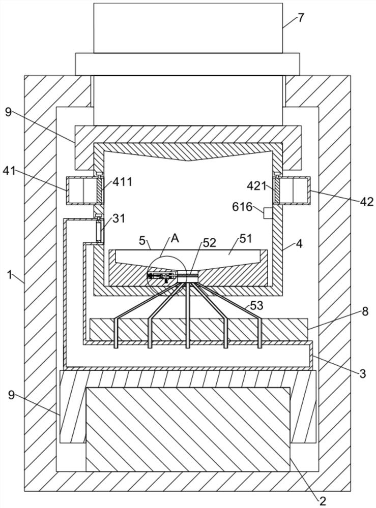
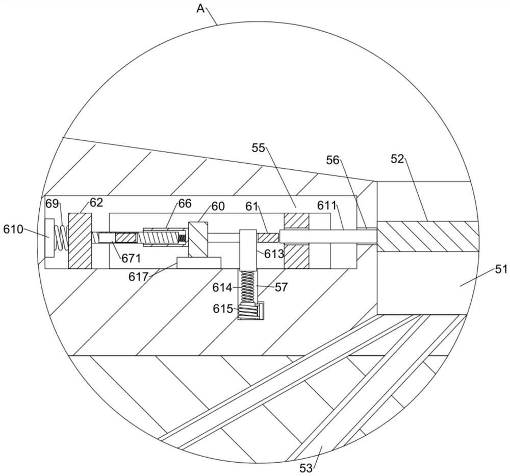
[0039] see Figure 1-9 , the present invention provides a technical solution:

[0040] A heat dissipation system for electrical equipment, including an electrical unit, a heat exchange unit and a refrigeration unit, the electrical unit includes an electrical box 1, and an electrical heating element 2 is arranged inside the electrical box 1;

[0041] The heat exchange unit includes an evaporation chamber 3, a condensation chamber 4 and a return box 5. The evap...


PUM


Abstract

The invention discloses a cooling system for electrical equipment, which includes an electrical unit, a heat exchange unit and a refrigeration unit. The heat exchange unit includes an evaporation chamber, a condensation chamber and a return box. The evaporation chamber communicates with the condensation chamber. The box is fixedly arranged at the bottom of the condensation chamber, and a coolant collection tank is provided in the reflux box, and a separator is movably connected inside the coolant collection tank, and a control mechanism is arranged inside the control mechanism tank. In use of the present invention, through The cooperation between the extrusion rod and each control plate realizes that the coolant is kept under a high pressure condition when condensing in the condensation chamber, and at the same time hinders the cooperation between the column, the extrusion spring and the electromagnet, and the cooling in the condensation chamber Only when the coolant is under high-pressure supercooling can the partition be opened, so that the coolant enters the capillary, which avoids the problem of low-pressure coolant entering the capillary and a large amount of "flash" phenomenon resulting in insufficient refrigeration efficiency.

Description

technical field [0001] The invention relates to the technical field of heat dissipation of electrical equipment, in particular to a heat dissipation system of electrical equipment. Background technique [0002] At present, the heat dissipation methods mainly include air convection cooling, liquid convection cooling, phase change evaporative cooling, semiconductor cooling and heat pipe heat conduction cooling, etc. The most widely used in the prior art are mainly air convection cooling and liquid convection cooling, but these two cooling The heat transfer efficiency of the method is low, and it is necessary to increase the heat dissipation parts to achieve the ideal cooling capacity, which brings great problems to the arrangement of the heat dissipation parts. [0003] In the prior art, the application number is "201811265139.3", an air-conditioning electrical box and its heat dissipation device, including a semiconductor cooling sheet, a heat insulation film and a heat sink,...

Claims


Application Information

Patent Timeline
Patent Type & Authority Patents(China)
IPC IPC(8): H05K7/20
CPCH05K7/20309H05K7/20318
Inventor 刘鑫雨杨小品任欣马哲宇穆阳罗燕来张文华王翠许惠君赵志英连晶晶
Owner SOUTH CHINA UNIV OF TECH
Learn More