Antenna, low frequency radiation unit and radiation arm

A technology of radiating element and radiating arm, applied in the structural form of radiating element, antenna, slot antenna, etc., can solve the problem of easily deteriorating the impedance characteristics of low-frequency radiation elements, achieve good matching characteristics, ensure matching characteristics, and suppress the generation of scattered signals Effect

Active Publication Date: 2021-09-24
COMBA TELECOM TECH (GUANGZHOU) CO LTD +1
View PDF8 Cites 0 Cited by
  • Summary
  • Abstract
  • Description
  • Claims
  • Application Information

AI Technical Summary

Problems solved by technology

[0003] Based on this, it is necessary to provide an antenna, a low-frequency radiation unit and a radiation arm for the problem of easily deteriorating the impedance characteristics of the low-frequency radiation unit

Method used


Image

  • Antenna, low frequency radiation unit and radiation arm
  • Antenna, low frequency radiation unit and radiation arm
  • Antenna, low frequency radiation unit and radiation arm

Examples


Embodiment Construction

[0044]In order to make the above objects, features, and advantages of the present invention, the specific embodiments of the present invention will be described in detail below with reference to the accompanying drawings. Many specific details are set forth in the following description to fully understand the present invention. However, the present invention can be implemented in many other fails there are many otherwise described herein, and those skilled in the art may do similar improvements without departing from the connotation of the present invention, and thus the present invention is not limited by the specific embodiments disclosed below.

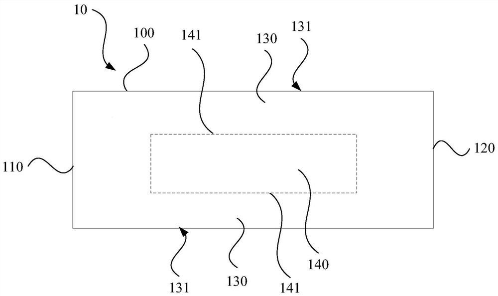
[0045] like figure 1 and figure 2 As shown in one embodiment, a radiator arm 10 is provided, which can be applied to the low frequency radiating unit of the antenna. The radiation arm 10 includes a radiation body 100, and the radiation body 100 is provided with a feed end 110, and the end 120 provided with the feed end 110, and is disp...


PUM


Abstract

The invention relates to an antenna, a low-frequency radiation unit and a radiation arm. The radiation arm includes a radiation body, and the radiation body is provided with a feeding end, an end set at a distance from the feeding end, and a terminal arranged at the feeding end. With the conductor segment between the end, a scattering suppression structure is provided in the contour area of ​​the conductor segment, and the scattering suppression structure has a current transmission path corresponding to the conductor segment, and the current transmission path is continuously arranged. The scattering suppression structure can not only suppress the intensity of the scattering signal, reduce the impact of the scattering signal on the performance index of the high-frequency radiation unit, but also reduce the impact on the impedance characteristics of the low-frequency radiation unit, which helps to maintain a good matching characteristic of the low-frequency radiation unit .

Description

Technical field [0001] The present invention relates to the field of mobile communication technologies, and more particularly to an antenna, a low frequency radiation unit, and a radiation arm. Background technique [0002] With the rapid development of mobile communication technology, the antenna is further developed toward miniaturization. In order to reduce the size of the antenna, the radiating units of different frequency bands can be close to each other to reduce the physical dimensions of the antenna. As such, the high-frequency radiating unit will excite the induced current in the low frequency radiating unit in its working state, in particular in an open electromagnetic field boundary due to the low frequency radiation unit radiation arm, and generates a scattering signal to affect high frequency radiation. The performance indicator of the unit. A conventional approach is to inhibit the scattering effect of the high-frequency radiation unit in the radiation arm of the lo...

Claims


Application Information

Patent Timeline
Patent Type & Authority Patents(China)
IPC IPC(8): H01Q1/36H01Q1/50H01Q1/52H01Q13/10
CPCH01Q1/36H01Q1/50H01Q1/521H01Q13/10
Inventor 赖展军徐慧俊薛锋章苏国生李明超刘培涛王强王宇郑之伦
Owner COMBA TELECOM TECH (GUANGZHOU) CO LTD
Why Eureka
Try Eureka