An Intelligent Pavement Crack Repair System
A technology for pavement cracks and cracks, applied in the field of intelligent pavement crack repair systems, can solve problems such as reducing repair efficiency and stopping, and achieve the effects of improving traffic safety, reducing data volume, and solving high labor costs.
- Summary
- Abstract
- Description
- Claims
- Application Information
AI Technical Summary
Problems solved by technology
Method used
Image
Examples
Embodiment 1
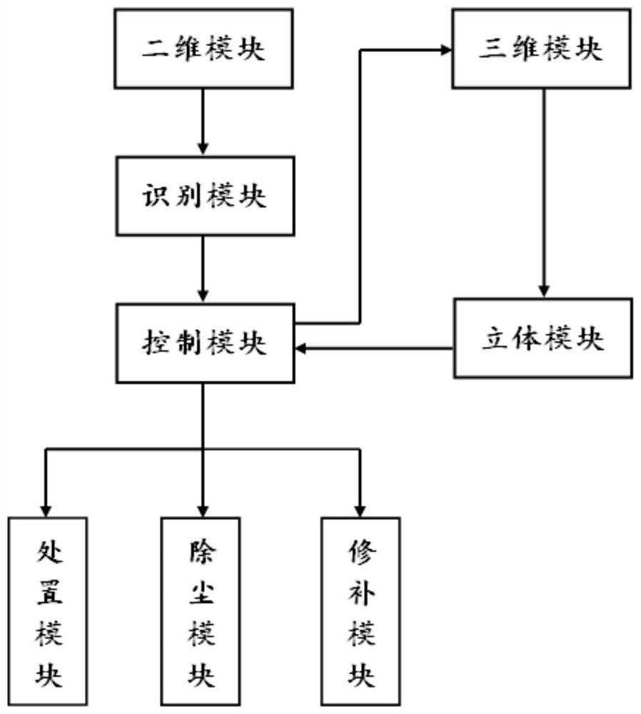
[0052] An embodiment of an intelligent pavement crack repair system of the present invention is basically as attached figure 1 shown, including:
[0053] The two-dimensional module is used to collect two-dimensional images of the road surface in real time;
[0054] 3D module for collecting 3D data of fractures;
[0055] The identification module is used to analyze the two-dimensional image of the road surface, determine whether there are cracks in the road surface, and determine the location information of the cracks when there are cracks in the road surface;
[0056] The control module is used to send the control signal for collecting the three-dimensional data of the crack and the control signal for reducing the vehicle speed when there are cracks on the road surface; send the control signal for slotting, send the control signal for dust removal, and send the control signal for repair;
[0057] The stereo module is used to establish a fracture stereo model according to the...
Embodiment 2
[0071] The only difference from Embodiment 1 is that the car cavity 7 of B is stored with emery, which is used to enhance the skid resistance of the repaired cracks. If the skid resistance of the repaired road surface does not meet the requirements, emery will flow out from the discharge port 8 of the B vehicle cavity and the valve 9 of the B vehicle cavity, and be laid on the road surface to improve the skid resistance coefficient.
Embodiment 3
[0073] The only difference from Embodiment 2 is that there are two two-dimensional scanning probes, including probe A and probe B, which are installed on the head of the vehicle; probe A and probe B are located on the same straight line and in the same direction as the vehicle is moving forward. In this embodiment, the deflection angles of probe A and probe B can vary between 30 and 60 degrees, and the deflection angle refers to the angle between the light emitted by the probe and the straight line perpendicular to the road surface. The probe deflects toward the front of the vehicle, deflecting angle is positive.
[0074] Initially, the deflection angles of probe A and probe B are both 30 degrees. When the vehicle is moving forward, the vehicle's driving speed is detected in real time, and the detected vehicle's driving speed is sent to the server. If the driving speed of the vehicle is between 0 and 30km / h, the server sends a signal to the control system so that the deflectio...
PUM
 Abstract
Description
Claims
Application Information
 - Generate Ideas
- Intellectual Property
- Life Sciences
- Materials
- Tech Scout
- Unparalleled Data Quality
- Higher Quality Content
- 60% Fewer Hallucinations
Browse by: Latest US Patents, China's latest patents, Technical Efficacy Thesaurus, Application Domain, Technology Topic, Popular Technical Reports.
© 2025 PatSnap. All rights reserved.Legal|Privacy policy|Modern Slavery Act Transparency Statement|Sitemap|About US| Contact US: help@patsnap.com


