
Device for equipment power failure reporting and power failure protection

A technology for power failure protection and equipment, applied in circuit devices, measurement devices, electrical components, etc., can solve problems affecting user experience, crash, black screen, etc., to achieve the effect of protecting labor results

Inactive Publication Date: 2020-12-29
OB TELECOM ELECTRONICS
View PDF5 Cites 1 Cited by
  • Summary
  • Abstract
  • Description
  • Claims
  • Application Information

AI Technical Summary

Problems solved by technology

[0002] When the current computing equipment encounters the external power failure, the main system will shut down abnormally due to power mismatch, because such abnormal shutdown will cause a lot of trouble to the operator
[0003] If it is a remote networked device, such as a traffic camera, a vending machine, etc., once a power failure occurs, the control port will lose communication and control of the remote device's networked device, and it is impossible to judge the status of the device in time, and it is also impossible to know the remote device. The reason why the networked device is disconnected, and maintenance personnel need to be dispatched to the site for diagnosis and repair to solve the problem
[0004] If it is a desktop computer and other equipment, the host will crash, blue screen, black screen, etc. due to insufficient power. can cause damage to hardware
[0005] If it is a portable device with its own power supply, such as a mobile phone, when the battery output power drops rapidly or the battery is exhausted, the mobile phone will automatically shut down, affecting the user experience

Method used


Image

  • Device for equipment power failure reporting and power failure protection
  • Device for equipment power failure reporting and power failure protection
  • Device for equipment power failure reporting and power failure protection

Examples


Embodiment 1

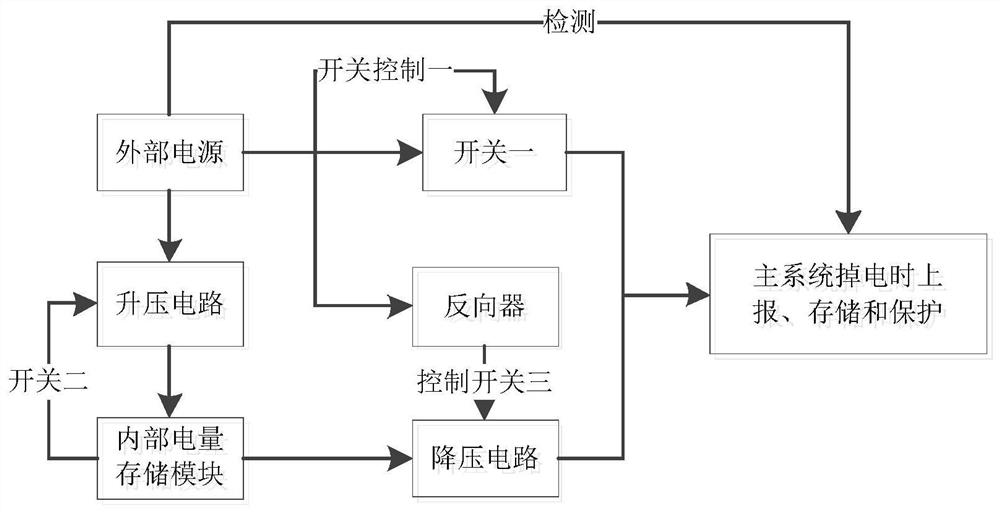
[0035] Such as figure 1 As shown in FIG. 1 , a device for power failure reporting and power failure protection includes: an external power supply, a boost module, an internal power storage module, an inverter, a voltage drop module, and a detection module. The external power supply is electrically connected to the electrical equipment and the internal power storage module; the booster module is set between the external power supply and the internal power storage module; the step-down module is set between the internal power storage module and the electrical equipment; reverse The detector is arranged between the external power supply and the step-down module; a detection module is also arranged between the external power supply and the electrical equipment.

[0036] The external power supply refers to an externally input power supply, that is, a power supply other than the internal power storage module, including batteries, 220V mains input, and other forms of power input.

...

Embodiment 2

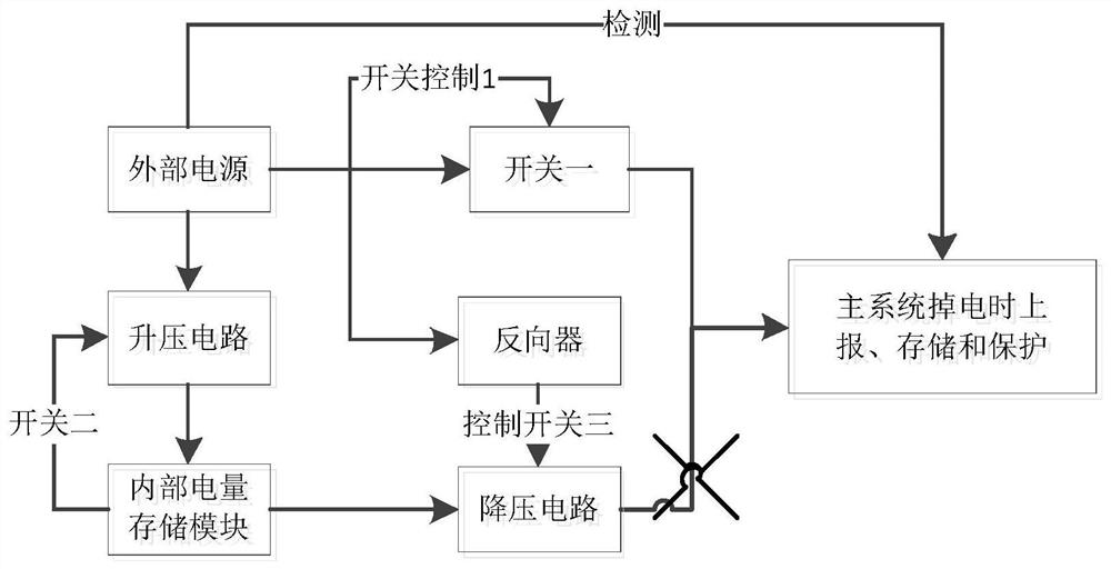
[0047] Such as Figure 4 As shown in FIG. 1 , a device for reporting power failure and power failure protection includes: an external power supply, an internal power storage module and a detection module. The external power supply is electrically connected to the electrical equipment and the internal power storage module; a detection module is also arranged between the external power supply and the electrical equipment.

[0048] A switch 1 is arranged between the external power supply and the electrical equipment, and the switch 1 is used to control the power supply and shutdown of the external power supply. The switch 1 is also electrically connected with the detection equipment, and the switch 1 is controlled by the detection equipment. A switch 3 is arranged between the internal power storage module and the electrical equipment, and the switch 3 is electrically connected with the detection equipment, and the switch 3 is controlled by the detection equipment. The switch thr...

Embodiment 3

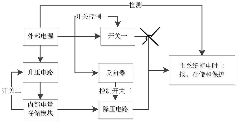
[0051] Such as Figure 5 As shown in FIG. 1 , a device for reporting power failure and power failure protection includes: an external power supply, a boost module, an internal power storage module, a voltage drop module, and a detection module. The external power supply is electrically connected to the electrical equipment and the internal power storage module; the booster module is set between the external power supply and the internal power storage module; the step-down module is set between the internal power storage module and the electrical equipment; the external power supply A detection module is also arranged between the electric device and the electric device. The step-up module includes a step-up circuit, and the step-down module includes a step-down circuit.

[0052] A switch 1 is arranged between the external power supply and the electrical equipment, and the switch 1 is used to control the power supply and shutdown of the external power supply. The switch 1 is al...


PUM


Abstract

The invention discloses a device for equipment power failure reporting and power failure protection. The device comprises an external power supply, a boosting module, an internal electric quantity storage module, an inverter, a voltage reduction module and a detection module; the external power supply is electrically connected with the electric equipment and the internal electric quantity storagemodule; the boosting module is arranged between the external power supply and the internal electric quantity storage module; the voltage reduction module is arranged between the internal electric quantity storage module and the electric equipment; the inverter is arranged between the external power supply and the voltage reduction module; a detection module is also arranged between the external power supply and the electric equipment; for remote networking equipment, uploading of a fault report can be realized through the internal electric quantity storage module, remote analysis is facilitated, targeted maintenance is performed, and the efficiency is improved; for a desktop computer and other equipment, an operator can have enough time to save files and turn off the computer, and the labor achievement of the operator is protected; aiming at portable equipment with a power supply, an auxiliary power supply is provided to satisfy power supply in emergency.

Description

technical field [0001] The invention relates to the field of power supply protection, in particular to a device for reporting power failure of equipment and for power failure protection. Background technique [0002] When the current computing equipment encounters the power failure of the external power supply, the main system will shut down abnormally due to power mismatch, because this kind of abnormal shutdown will cause many troubles to the operators. [0003] If it is a remote networked device, such as a traffic camera, a vending machine, etc., once a power failure occurs, the control port will lose communication and control of the remote device's networked device, and it is impossible to judge the status of the device in time, and it is also impossible to know the remote device. The reason for the disconnection of networked equipment requires sending maintenance personnel to the site for diagnosis and repair to solve the problem. [0004] If it is a desktop computer a...

Claims


Application Information

Patent Timeline
Patent Type & Authority Applications(China)
IPC IPC(8): H02J9/06G06F1/26G06F1/30
CPCH02J9/068H02J9/061G06F1/263G06F1/30
Inventor 石旭刚章云斌
Owner OB TELECOM ELECTRONICS
Learn More