Satellite and inertia combined dynamic-to-dynamic real-time precise relative positioning method

A relative positioning and inertial combination technology, applied in satellite radio beacon positioning systems, measuring devices, instruments, etc., can solve the communication pressure and calculation burden without considering centimeter-level relative positioning solutions, data broadcast rate and sampling rate And other issues

Active Publication Date: 2020-12-29
NAT UNIV OF DEFENSE TECH
View PDF8 Cites 5 Cited by
  • Summary
  • Abstract
  • Description
  • Claims
  • Application Information

AI Technical Summary

Problems solved by technology

However, these methods all need to broadcast the original inertial navigation measurement information, without considering the communication pressure and calculation burden caused by the data broadcas

Method used


Image

  • Satellite and inertia combined dynamic-to-dynamic real-time precise relative positioning method
  • Satellite and inertia combined dynamic-to-dynamic real-time precise relative positioning method
  • Satellite and inertia combined dynamic-to-dynamic real-time precise relative positioning method

Examples


Embodiment 1

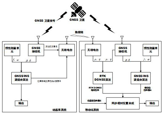
[0068] refer to figure 1 , a kind of satellite and inertial combined moving-to-moving real-time precise relative positioning method comprises the following steps:

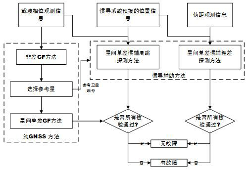
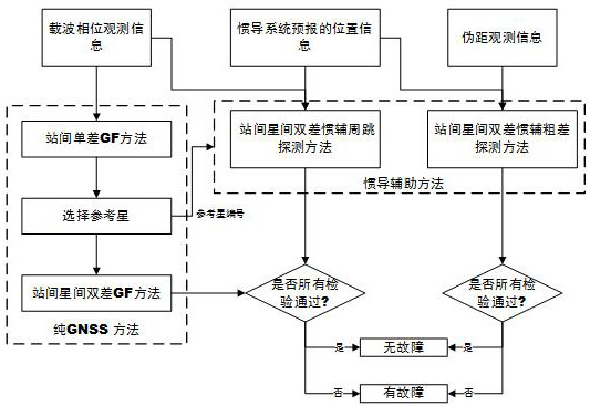
[0069] In the first step, the mobile station receiver and the moving reference receiver sample synchronously to obtain the original GNSS observation information, respectively detect and eliminate the fault information gross error of carrier phase cycle slip and pseudo-range observation information in the original GNSS observation information obtained by sampling respectively, and obtain The preprocessed carrier phase and pseudorange observation information of the mobile station receiver and the moving reference receiver.

[0070] The invention adopts multiple methods to jointly detect and eliminate faults. Gross errors in GNSS observation data must be monitored and eliminated before being used for relative positioning. Fault information includes carrier phase cycle slip and pseudorange gross error. Carrier phas...

Embodiment 2

[0161] In order to test the method in Example 1, a vehicle-to-vehicle test is carried out in this example. The mobile station and the moving reference are both vehicles and there are many turns when moving on the square. A static reference station is set up at a known location near the test site to calculate the relative positions of the mobile station and the moving reference post-processing respectively. The corresponding results are used to provide reference results for position increments and relative positions. In the test, the GNSS / MEMS prototype system consisting of Sensonor STIM300 MEMS and ComNavOEM-K508 board is fixedly connected to the No. 2 mobile datum of the mobile station. The GNSS receiver can provide observation information of 5 frequency points (B1 / B2 / B3 / L1 / L2) for real-time and post-navigation. In the subsequent analysis, only the observation information of four frequency points (B1 / B3 / L1 / L2) is actually used. The maximum sampling rate of the GNSS receive...


PUM


Abstract

The invention provides a satellite and inertia combined dynamic-to-dynamic real-time precise relative positioning method. The method comprises the following steps of: acquiring a relative positioningvector between a mobile station and a dynamic reference based on a carrier phase real-time dynamic differential relative positioning method; acquiring a mobile station position increment, a dynamic reference position increment and a position increment of the mobile station within a measurement updating time interval delta tTC based on a carrier phase GNSS/inertial navigation tight combination algorithm; and acquiring the dynamic reference position increment within a forecast time delta tp based on a polynomial forecast method of a sliding window; and finally synthesizing and outputting a relative positioning result. The method can overcome the influence caused by the position increment and GNSS original observation data broadcast delay, and can provide a precise relative positioning resultwith an extremely high update rate through a low data broadcast rate and a sampling rate.

Description

technical field [0001] The invention belongs to the technical field of satellite and inertial combination relative positioning and navigation, in particular to a satellite and inertial combination dynamic-to-dynamic precise relative positioning method with low data broadcast rate, low sampling rate and extremely high update rate. Background technique [0002] Precise relative positioning with high update rates is a required technology in many safety-related motion-to-motion applications, such as vehicle-to-vehicle cooperative safety applications, autonomous aerial refueling, and carrier-based aircraft landing. At present, the commonly used motion-to-motion relative positioning technology is the carrier phase RTK (Real-Time Kinematic) differential relative positioning technology. However, the use of carrier phase RTK (Real-Time Kinematic) differential relative positioning technology to achieve high update rate output is mainly due to the high data broadcast rate, high receive...

Claims


Application Information

Patent Timeline
IPC IPC(8): G01S19/47G01S19/44G01C21/16
CPCG01C21/165G01S19/44G01S19/47
Inventor 李青松吴杰董毅王鼎杰
Owner NAT UNIV OF DEFENSE TECH
Why Eureka
Try Eureka