Rapid fabricated house and mounting method

An installation method and prefabricated technology, which are applied in the field of quick prefabricated houses and installations, can solve the problems of time-consuming installation, inconvenient installation, and inability to disassemble steel structure houses, and achieve the effect of improving efficiency and reducing assembly and disassembly time.

Inactive Publication Date: 2020-12-29
抚州市恒强达绿色建筑科技有限公司
View PDF7 Cites 4 Cited by
  • Summary
  • Abstract
  • Description
  • Claims
  • Application Information

AI Technical Summary

Problems solved by technology

[0005] In view of the above situation, in order to overcome the defects of the prior art, the present invention provides a quick-assembled house and an installation method, which effectively solves the problem that the steel structure house in the above-mentioned background technology needs to use a large number of threaded nails when assembling and connecting. Inconvenience, and it takes a lot of time to install, and at the same time, it is impossible to disassemble the steel structure house quickly and conveniently

Method used


Image

  • Rapid fabricated house and mounting method
  • Rapid fabricated house and mounting method
  • Rapid fabricated house and mounting method

Examples


Embodiment 1

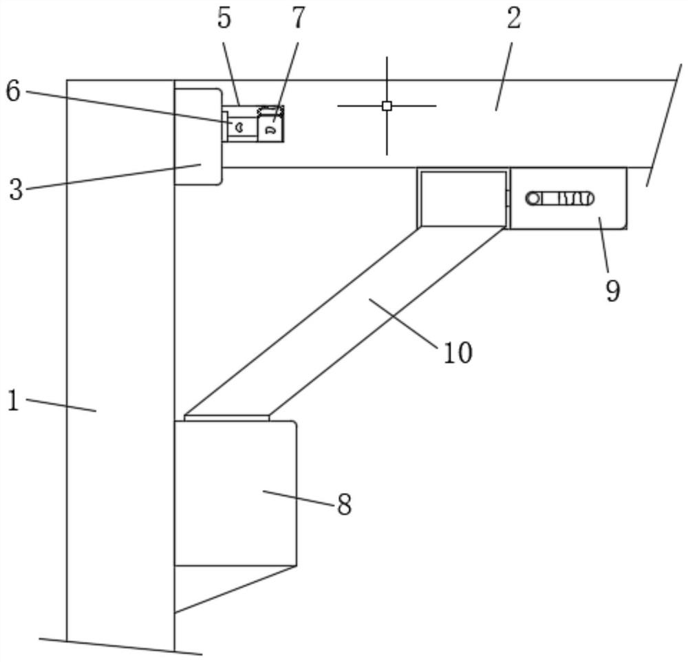
[0033] Embodiment one, by Figure 1 to Figure 6 Given, the present invention includes a steel structure column 1 and a steel structure beam 2, the upper part of the steel structure column 1 is fixedly installed with a U-shaped steel clip 3, and the upper part of the steel structure column 1 is located inside the U-shaped steel clip 3. The socket 4 is fixed, and the end of the steel structure beam 2 is movably clamped inside the U-shaped steel clip 3, so that the steel structure beam 2 can be stably connected with the steel structure column 1, and the two sides of the steel structure beam 2 Both ends are provided with a groove 5, one end of the groove 5 is installed with a fixed plug-in 6, one end of the fixed plug-in 6 is movably inserted into the fixed socket 4, and the other end of the groove 5 is equipped with a fixed stop 7, the steel structure The lower part of the column 1 is fixedly installed with the first fixed block 8, and the bottom of the steel structure beam 2 is ...

Embodiment 2

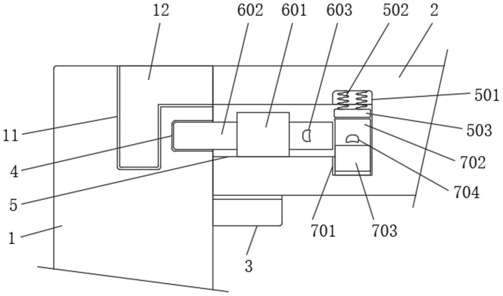
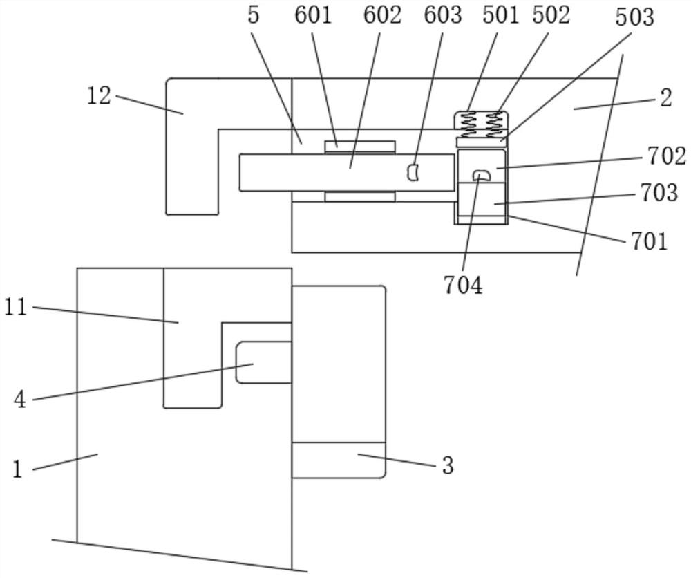
[0034] Embodiment two, on the basis of embodiment one, by figure 2 and image 3 Given, the top of the steel structure column 1 is provided with an L-shaped slot 11, the end of the steel structure beam 2 is fixedly connected with an L-shaped insert 12, and the L-shaped insert 12 is movably inserted into the inside of the L-shaped slot 11, Therefore, the steel structure beam 2 can maintain the stability of the lateral connection.

Embodiment 3

[0035] Embodiment three, on the basis of embodiment one, by figure 2 and image 3 Given, the fixed insert 6 includes a U-shaped piece 601, an insertion rod 602 and a first toggle block 603, the U-shaped piece 601 is fixedly installed at one end of the groove 5, and the insertion rod 602 is movably inserted into the inside of the U-shaped piece 601, The first toggle block 603 is fixedly installed on one side of the insertion rod 602, and one end of the insertion rod 602 is movably inserted into the fixed socket 4, so that the steel structure beam 2 can maintain the stability of the vertical connection.


PUM


Abstract

The invention relates to the technical field of houses, discloses a rapid fabricated house and a mounting method. The problems that a large number of threaded nails are required to be used when a steel structure house is assembled and connected, consequently, mounting is inconvenient, a large amount of time is required to be spent in mounting, and meanwhile the steel structure house cannot be disassembled rapidly and conveniently are solved. The rapid fabricated house comprises a steel structure column and a steel structure beam, a U-shaped steel clamping piece is fixedly mounted on the upperportion of the steel structure column, a fixed inserting hole is formed in the position, located on the inner side of the U-shaped clamping piece, of the upper portion of the steel structure column, the end of the steel structure beam is movably connected in the U-shaped steel clamping piece in a clamped manner, grooves are formed in the two ends of the two sides of the steel structure beam, and afixed inserting piece is mounted at one end of each groove. The rapid fabricated house is assembled in a connection manner of clamped connection and inserted connection, meanwhile, the rapid fabricated house can be rapidly and conveniently disassembled in the connection manner of clamped connection and inserted connection, and therefore the house assembling and disassembling efficiency is effectively improved, and the house assembling and disassembling time is shortened.

Description

technical field [0001] The invention belongs to the technical field of houses, in particular to a rapidly assembled house and an installation method. Background technique [0002] Buildings assembled from prefabricated parts on site are called prefabricated buildings; at present, in order to shorten the construction period and improve construction quality in construction projects, prefabricated structures are often used. Prefabricated structures are divided into two types; reinforced concrete prefabricated structures and prefabricated structures. Steel structure; the first type of prefabricated structure reinforced concrete generally uses prefabricated structural parts to leave steel bar heads at the joints. After the on-site assembly, the joints are supported and then the joints are poured, and the joints are fixed by maintenance on site. The second type of prefabricated structure is generally used as a permanent building. The second type of prefabricated structure is to us...

Claims


Application Information

Patent Timeline
IPC IPC(8): E04B1/00E04B1/58E04C3/32E04C3/04E04G21/14
CPCE04B1/00E04B1/58E04C3/04E04C3/32E04G21/14
Inventor 汪志强
Owner 抚州市恒强达绿色建筑科技有限公司
Why Eureka
Try Eureka