
A new energy charging pile with buffer and protection functions

A protection function and charging pile technology, applied in the field of new energy charging piles, can solve the problems of waste of materials, no anti-collision, large space occupation, etc., and achieve the effect of preventing damage and improving the effect of collision and energy absorption.

Active Publication Date: 2022-06-03
浙江晨泰科技股份有限公司
View PDF6 Cites 0 Cited by
  • Summary
  • Abstract
  • Description
  • Claims
  • Application Information

AI Technical Summary

Problems solved by technology

However, the number of charging piles is growing rapidly, but because public charging facilities generally have the characteristics of "high-voltage charging, outdoor placement, and unattended", the current safety concerns of charging piles still exist
At present, the existing new energy charging piles do not have the function of anti-collision, so that when the new energy vehicles collide with the new energy charging piles, it is easy to cause damage to the new energy charging piles
The anti-collision part of some new energy charging piles is set near the periphery of the charging pile, which occupies a large space; some new energy charging piles are fully equipped with buffer materials around the pile body in order to avoid collisions, and the materials are wasteful; even some new energy charging piles The energy charging pile can better protect the charging pile, but it is powerless to further expand the damage caused by the accident such as collision and electric shock

Method used


Image

  • A new energy charging pile with buffer and protection functions
  • A new energy charging pile with buffer and protection functions
  • A new energy charging pile with buffer and protection functions

Examples


Embodiment Construction

[0025] In order to make the technical means, creative features, achievement goals and effects realized by the present invention easy to understand, the present invention will be further described below with reference to the specific embodiments.

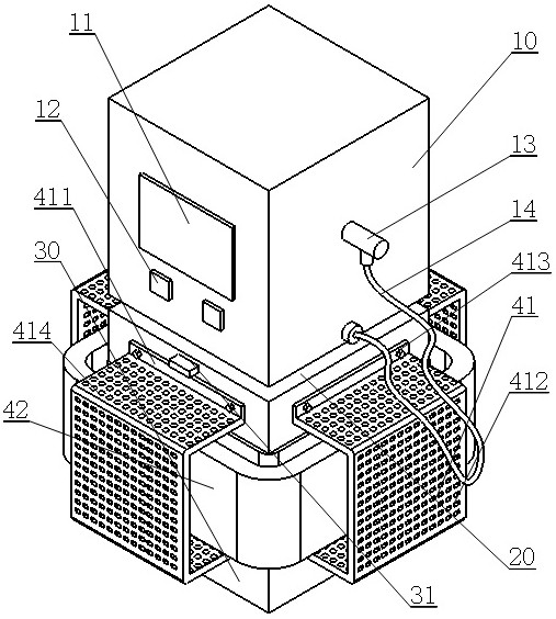
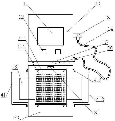
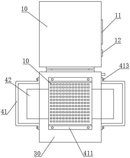
[0026] like Figure 1-8 As shown, a new energy charging pile with buffering and protection functions includes:

[0027] The box body 10 is located on the upper part of the new energy charging pile. A display screen 11 and two card swiping areas 12 are fixedly connected to the front of the box body 10. A charging gun 13 and a charging cable 14 are fixedly connected to the right side of the box body 10. The bottom of 10 has a square base 15 with an area slightly smaller than the bottom. The base 15 is integrally formed with the box body 10, and the base 15 is hollow. The interior of the base 15 can be used as a receiving cavity. Used to support the box 10 .

[0028] The connecting part 20 is located in the middle of the new energy ch...


PUM


Abstract

The invention discloses a new energy charging pile with buffering and protection functions, which includes a box body, a connecting part and a base body; The charging gun and the charging cable are connected, and the base is hollow at the bottom; the connecting part is located in the middle of the charging pile, and the connecting part has a shell and an inner cavity, and the inner cavity of the connecting part is placed with an airbag; the base is located at the lower part of the charging pile, and the There are pressure sensor, gas generator, power controller and three anti-collision parts; when the pressure of the first anti-collision part exceeds the threshold value, the pressure sensor sends a gas release signal to the gas generator, and the second anti-collision part sends a signal to the third anti-collision part. The collision part conducts pressure, and when the pressure of the third anti-collision part exceeds a threshold value, the pressure sensor sends a signal to cut off the power supply to the power controller. The invention not only saves materials, is convenient for replacement, but also realizes multi-directional protection for charging piles and collision vehicles.

Description

technical field [0001] The invention relates to the technical field of charging pile equipment, in particular to a new energy charging pile with buffering and protection functions. Background technique [0002] As a representative of green transportation, new energy vehicles have many advantages of energy saving, environmental protection and cleanliness compared with traditional fuel vehicles, and at the same time, the economic cost and environmental protection cost are very low. New energy vehicles are widely accepted by people. In the contemporary era of development, the most important charging piles on new energy vehicles have also become an indispensable part. However, the number of charging piles has grown rapidly, but due to the common characteristics of "high voltage charging, placed outdoors, and unattended" in public charging facilities, the current safety concerns of charging piles still exist. At present, the existing new energy charging piles do not have the fun...

Claims


Application Information

Patent Timeline
Patent Type & Authority Patents(China)
IPC IPC(8): B60L53/31F16F15/02F16F15/08F16F15/023
CPCB60L53/31F16F15/02F16F15/08F16F15/023Y02T90/12
Inventor 何伟
Owner 浙江晨泰科技股份有限公司
Learn More