
Automatic discharging printing machine for environment-friendly bag processing

A technology of automatic unloading and environmental protection bags, applied to printing machines, rotary printing machines, printing, etc., can solve the problems of inconsistent pattern positions, low work efficiency, troublesome operation, etc., and achieve consistent pattern positions, convenient operation, and high work efficiency Effect

Active Publication Date: 2020-12-29
日照坤钰包装科技有限公司
View PDF14 Cites 0 Cited by
  • Summary
  • Abstract
  • Description
  • Claims
  • Application Information

AI Technical Summary

Problems solved by technology

[0005] In order to overcome the shortcomings that human hands need to operate back and forth to print patterns on the environmental protection bag, the operation is cumbersome, the work efficiency is low, and the position of the environmental protection bag is prone to deviation, resulting in inconsistent positions of the printed patterns, the technical problem of the present invention is: to provide a It is an automatic unloading printing machine for environmental protection bag processing that can replace people to print environmental protection bags, is easy to operate, high in work efficiency, and has the same printed pattern position

Method used


Image

  • Automatic discharging printing machine for environment-friendly bag processing
  • Automatic discharging printing machine for environment-friendly bag processing
  • Automatic discharging printing machine for environment-friendly bag processing

Examples


Embodiment 1

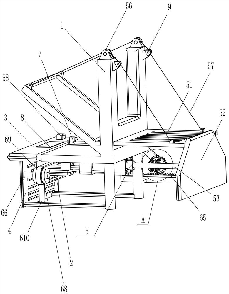
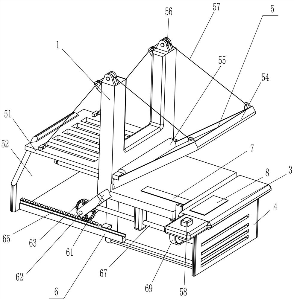
[0021] An automatic unloading printing machine for environmental protection bag processing, such as figure 1 and figure 2 As shown, it includes an L-shaped plate 1, a u-shaped fixed block 2, an operation plate 3, a support plate 4 and a printing mechanism 5, and the front and rear sides of the outer bottom of the L-shaped plate 1 are symmetrically fixed with a u-shaped fixed block 2, and the front and rear sides An operation panel 3 is affixed between the top of the right side of the u-shaped fixed block 2, a support plate 4 is affixed to the bottom of the operation panel 3, and a printing mechanism 5 is arranged between the left part of the L-shaped plate 1.

[0022] The printing mechanism 5 includes a multi-slot plate 51, a fixed plate 52, a cylinder 53, a printing plate 54, a cylinder 55, a wire pulley 56, a pull cord 57 and a button 58, and the lower part of the left side of the L-shaped plate 1 slides through the multi-slot plate 51, the left side of the multi-slot plat...

Embodiment 2

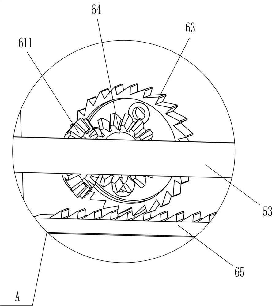
[0026] On the basis of Example 1, such as Figure 1-Figure 3 As shown, transmission mechanism 6 is also included, and transmission mechanism 6 includes L-shaped bar 61, fixed rod 62, ratchet 63, first bevel gear 64, ratchet bar 65, transmission shaft 67, cross bar 66, pulley 68, flat belt 69. The pushing block 610 and the second bevel gear 611, the L-shaped bar 61 is fixedly connected to the left side of the lower part of the front side of the L-shaped plate 1, and the lower part of the L-shaped bar 61 is rotatably connected to the fixed rod 62, and the middle part of the fixed rod 62 is fixed in the circumferential direction. A ratchet 63 is connected, a first bevel gear 64 is fixedly connected to the rear of the fixed rod 62 in the circumferential direction, a ratchet strip 65 is fixedly connected to the lower front side of the right side of the fixed plate 52, and the ratchet strip 65 and the ratchet 63 are meshed. There is a transmission shaft 67 in the middle of the front...

Embodiment 3

[0029] On the basis of embodiment 1 and embodiment 2, such as figure 1 and figure 2 As shown, a first rubber block 7 and a second rubber block 8 are also included, the first rubber block 7 is affixed to the front side of the inner bottom of the L-shaped plate 1 , and the second rubber block 8 is affixed to the front side of the top of the operation panel 3 .

[0030] Also include guide wheel 9, L-shaped plate 1 outer left side top, front and rear sides are all fixedly connected with guide wheel 9, and guide wheel 9 contacts and cooperates with stay cord 57.

[0031] When the environmental protection bag is placed on the L-shaped board 1, the environmental protection bag is contacted with the first rubber block 7 and the second rubber block 8, and the first rubber block 7 and the second rubber block 8 limit the environmental protection bag, so that the The position of the environmental protection bag is consistent every time, which makes the position of the printed pattern co...


PUM


Abstract

The invention relates to a printing machine, and particularly relates to an automatic discharging printing machine for environment-friendly bag processing. The automatic discharging printing machine for environment-friendly bag processing can replace people to print environment-friendly bags, and is convenient to operate, high in working efficiency and consistent in printed pattern position. The automatic discharging printing machine for environment-friendly bag processing comprises an L-shaped plate and an operation plate, wherein u-shaped fixing blocks are symmetrically installed on one sideoutside the L-shaped plate, and the operation plate is fixedly connected between the ends of the two u-shaped fixing blocks close to the L-shaped plate. According to the automatic discharging printing machine for environment-friendly bag processing, the environment-friendly bags are placed on the L-shaped plate, a button is pressed, an air cylinder is started, a printing plate swings downwards tomake contact with the environment-friendly bags, a roller moves rightwards to print patterns on the environment-friendly bags, after pattern printing is completed, the printing plate swings upwards to reset, and therefore the environment-friendly bags can be rapidly printed, operation is convenient, and the working efficiency is high.

Description

technical field [0001] The invention relates to a printing machine, in particular to an automatic unloading printing machine for environmental protection bag processing. Background technique [0002] Environmental bag is a kind of green product, tough and durable, beautiful in shape, good air permeability, reusable, washable, silk screen advertising, long service life, suitable for any company and any industry as advertising and gifts. Environmentally friendly bags are more economical. Starting from the release of the plastic restriction order, plastic bags will gradually withdraw from the packaging market for goods and will be replaced by environmentally friendly bags that can be used repeatedly. Compared with plastic bags, environmental protection bags are easier to print patterns, and the color expression is more vivid. In addition, it can be used repeatedly. You can consider adding more exquisite patterns and advertisements on the environmental protection bags than plas...

Claims


Application Information

Patent Timeline
Patent Type & Authority Applications(China)
IPC IPC(8): B41F17/00B65G47/82
CPCB41F17/00B65G47/82
Inventor 简政
Owner 日照坤钰包装科技有限公司
Learn More