Main shaft transmission arrangement structure of vertical lathe

A technology of spindle drive and layout structure, which is applied in the direction of driving devices, turning equipment, turning equipment, etc., can solve the problems of complicated design of the working turntable, troublesome precision adjustment, and large space occupation, and achieves simple design of the turntable, compact structure, and low cost. The effect of installation space

Pending Publication Date: 2020-12-29
浙江日发精密机床有限公司
View PDF6 Cites 0 Cited by
  • Summary
  • Abstract
  • Description
  • Claims
  • Application Information

AI Technical Summary

Problems solved by technology

[0004] Aiming at the problems existing in the existing machine tool spindle drive layouts that the equipment occupies a large space, the design of the working turntable is relatively complicated, the weight is large, the center of gravity is high, and the precision adjustment is troublesome, the present invention aims to provide a compact structure, high transmission efficiency, and easy operation. Reliable spindle layout structure of vertical lathe spindle transmission layout structure

Method used


Image

  • Main shaft transmission arrangement structure of vertical lathe
  • Main shaft transmission arrangement structure of vertical lathe
  • Main shaft transmission arrangement structure of vertical lathe

Examples


Embodiment Construction

[0020] Specific embodiments of the present invention will be described in detail below in conjunction with the accompanying drawings.

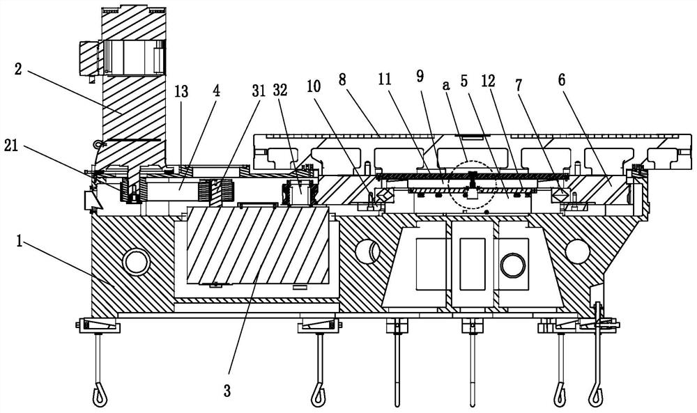
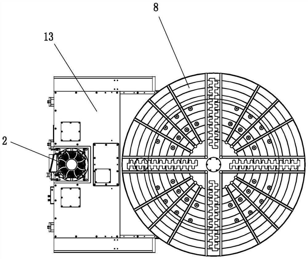
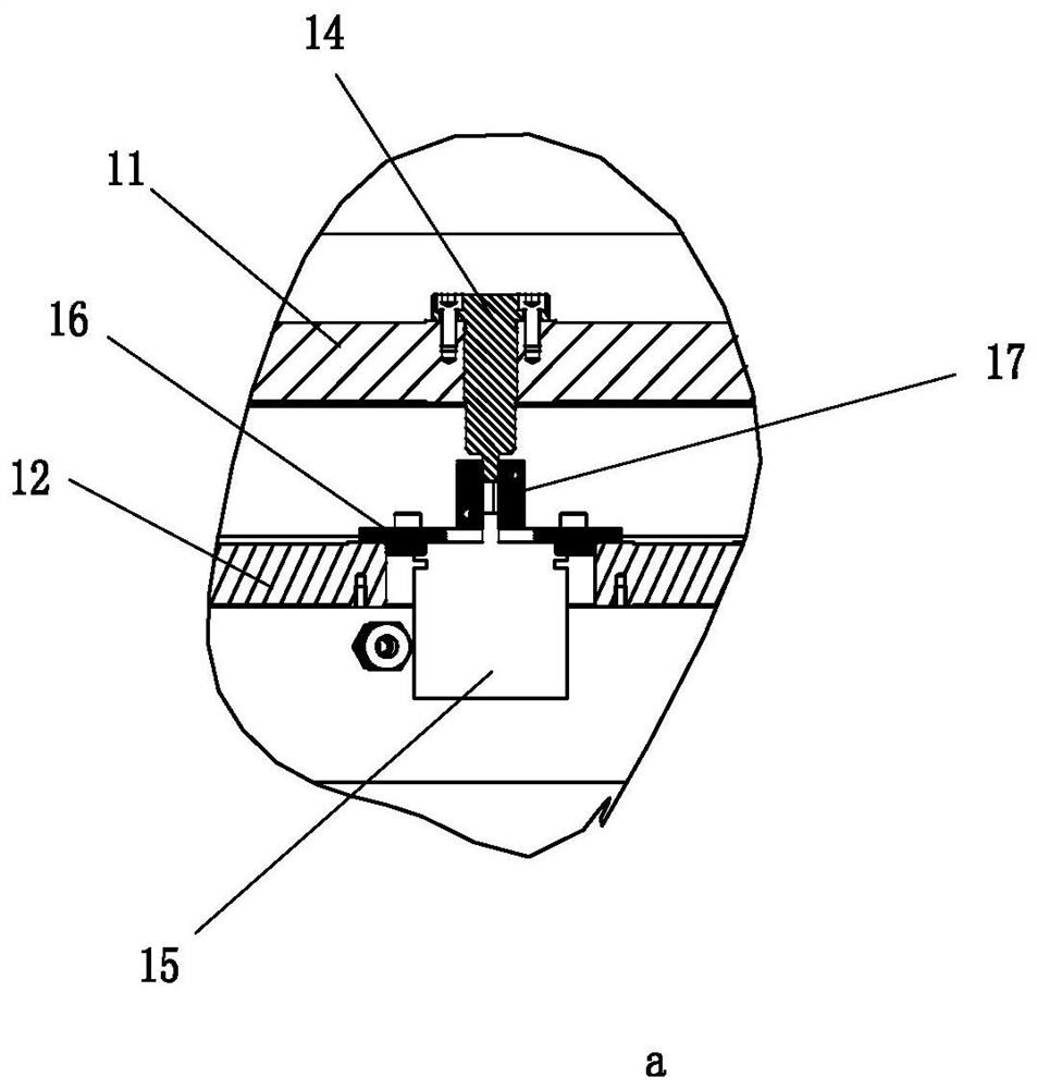
[0021] Such as Figure 1-Figure 3 As shown, the present invention comprises motor 2, reduction box 3, main shaft 5 and transmission ring gear 6, and motor 2 is installed by motor mounting plate, and the motor shaft 21 of motor 2 faces downward, and the speed reduction box installation groove is formed on the lathe bed 1, and reduction box The input shaft 31 and the output shaft 32 of 3 face upward and face the motor shaft 21, the input shaft 31 of the reduction box 3 and the motor shaft 21 are connected through the pulley and the belt 4; the main shaft 5 is supported and installed in the transmission ring gear 6 , The output shaft 32 of the reduction box 3 is set with a gear, and the outer peripheral portion of the transmission ring gear 6 is meshed with the gear. A workbench 8 is arranged on the top end surface of the transmission ring gear ...


PUM


Abstract

The invention discloses a main shaft transmission arrangement structure of a vertical lathe. The main shaft transmission arrangement structure comprises a motor, a reduction gearbox, a main shaft anda transmission gear ring, wherein the motor is mounted through a motor mounting plate; a motor shaft of the motor faces downwards; a reduction gearbox mounting groove is formed in a lathe body; an input shaft and an output shaft of the reduction gearbox face upwards and are directly opposite to the motor shaft; the input shaft of the reduction gearbox is in transmission connection with the motor shaft through a belt wheel and a belt; the main shaft is mounted in the transmission gear ring through a bearing support; a gear is arranged on the output shaft of the reduction gearbox in a sleeving manner; and the peripheral part of the transmission gear ring is meshed with the gear. According to the main shaft transmission arrangement structure, the motor shaft is mounted in an inverted manner,and a mounting space for mounting a transmission mechanism and the reduction gearbox is formed in the lathe body, so that the mounting space of a mounting part of the vertical lathe is greatly reduced, the structure is relatively compact, and the transmission efficiency is greatly improved.

Description

technical field [0001] The invention belongs to the technical field of vertical lathe main shaft transmission, and particularly relates to an arrangement structure suitable for vertical lathe main shaft transmission. Background technique [0002] As the core part of the machine tool, the spindle's rotation accuracy will directly affect the roundness, cylindricity, runout and other accuracy of the processed parts. [0003] At present, the traditional arrangement of spindle drive: the installation position of the main motor is separated from the bed, and the power is transmitted through a long V-belt. In addition, the spindle positioning support structure is composed of double-row cylindrical roller bearings + thrust ball bearings, of which the double-row cylindrical roller bearings are the main support; the thrust cylindrical roller bearings mainly carry the weight of the workpiece and load it on the worktable during the cutting process cutting force. This type of spindle d...

Claims


Application Information

Patent Timeline
IPC IPC(8): B23Q5/10B23B3/06
CPCB23Q5/10B23B3/06
Inventor 张小雨何晓峰孙敏敏
Owner 浙江日发精密机床有限公司
Why Eureka
Try Eureka