
Transparent conductive film and manufacturing method thereof

A technology of a transparent conductive film and a manufacturing method, which is applied in the manufacture of cables/conductors, conductive layers on insulating carriers, and equipment for manufacturing conductive/semi-conductive layers, etc., can solve the problem of low product quality and poor bonding effect. , the difficulty of fitting, etc., to achieve the effect of improving conductivity, reducing thickness and processing difficulty, and facilitating fitting

Pending Publication Date: 2020-12-25
SUZHOU WEIYEDA TOUCH TECH +1
View PDF0 Cites 0 Cited by
  • Summary
  • Abstract
  • Description
  • Claims
  • Application Information

AI Technical Summary

Problems solved by technology

Almost all these conductive films need to be bonded with optical glue during use, so it is easy to cause air bubbles between the conductive film and the bonded product during the bonding process, the bonding effect is not good, and the product quality is not high; At the same time, it is more difficult to fit, resulting in an increase in cost

Method used


Image

  • Transparent conductive film and manufacturing method thereof
  • Transparent conductive film and manufacturing method thereof
  • Transparent conductive film and manufacturing method thereof

Examples


no. 1 example

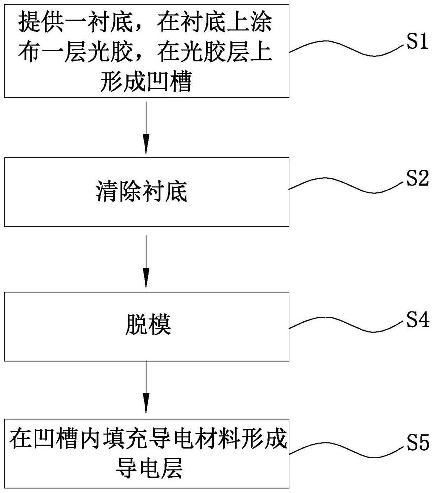
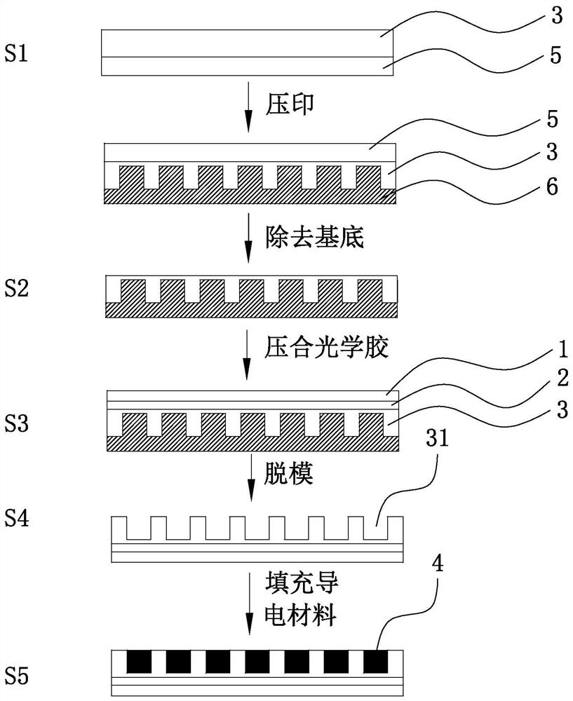
[0035] Please refer to Figure 2 to Figure 3 , the method for making the transparent conductive film provided in the first embodiment of the present invention is used to make the above transparent conductive film, the method comprising:

[0036] S1: Provide a substrate 5, coat a layer of photoresist on the substrate 5, and form grooves 31 on the photoresist layer 3;

[0037] S2: remove the substrate 5;

[0038] S3: providing an optical adhesive film, including an optical adhesive layer 2 and a base film 1, and laminating the optical adhesive film on the optical adhesive layer 3;

[0039] S5: filling the groove 31 with a conductive material to form the conductive layer 4 .

[0040] In this method, the photoresist is UV photoresist.

[0041] In step S1: use the mold 6 to emboss on the photoresist, so that the mold 6 and the photoresist are pasted together. A photoresist layer 3 with grooves 31 is formed after being cured by UV light.

[0042] In step S2 : manually separate ...

no. 2 example

[0046] The difference between the transparent conductive film method provided by the second embodiment of the present invention and the above-mentioned first embodiment is that in this embodiment, the optical adhesive is directly coated on the optical adhesive film.

[0047] Specifically, please refer to Figure 4 , the transparent conductive film method provided by the second embodiment of the present invention is used to make the above transparent conductive film, the method includes:

[0048] S7: providing an optical adhesive film, including an optical adhesive layer and a base film, and preparing an optical adhesive layer with grooves on the optical adhesive film;

[0049] S8: filling the groove with a conductive material to form a conductive layer;

[0050] In step S7: Firstly, by coating, a layer of optical adhesive is coated on the surface of the optical adhesive layer away from the base film to form an optical adhesive layer. Then use the mold to emboss on the photor...


PUM

PropertyMeasurementUnit
widthaaaaaaaaaa
depthaaaaaaaaaa
thicknessaaaaaaaaaa

Abstract

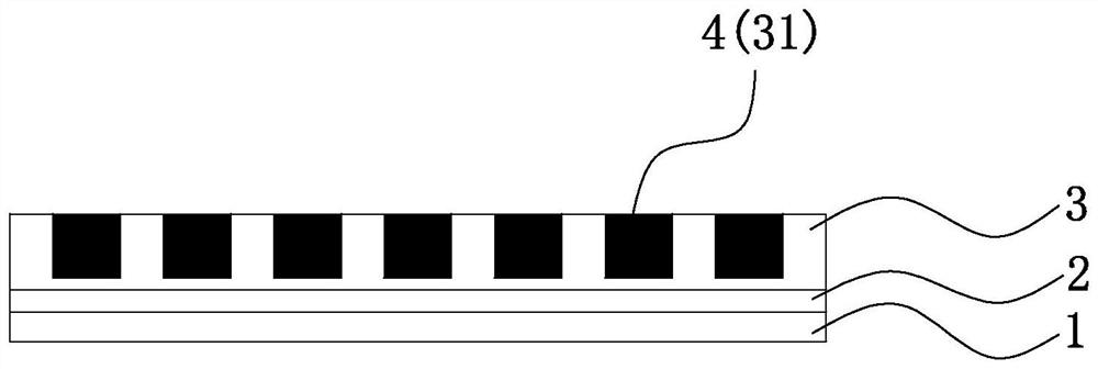
The invention discloses a transparent conductive film which comprises an optical cement layer, a base film and an optical cement layer, the optical cement layer is arranged on the surface of the optical cement layer, the base film is arranged on the surface of the other side, away from the optical cement layer, of the optical cement layer, a groove is formed in the surface, away from the optical cement layer, of the optical cement layer, and a conductive layer is arranged in the groove. The invention also discloses a manufacturing method of the transparent conductive film, which is used for manufacturing the transparent conductive film. Through the optical adhesive layer, lamination of the transparent conductive film is greatly facilitated, and the problems of poor lamination effect and high lamination difficulty during lamination of an existing transparent conductive film are effectively solved; and meanwhile, the groove is formed and filled with the conductive material to form the conductive layer, so that the conductivity, transmittance and bending resistance of the transparent conductive film are greatly improved while the flexibility of the transparent conductive film is ensured, the thickness and processing difficulty of the transparent conductive film are reduced, and the cost is reduced.

Description

technical field [0001] The invention relates to the technical field of conductive films, in particular to a transparent conductive film and a manufacturing method thereof. Background technique [0002] Existing metal grid conductive films generally need to be processed on one layer of substrate, and the substrate is generally glass, high molecular polyester (PET, PC, PMMA, etc.). The conductive film is prepared by embossing grooves on the substrate and then filled with conductive materials, and the conductive film is also prepared by inkjet printing conductive materials on the substrate. Almost all these conductive films need to be bonded with optical glue during use, so it is easy to cause air bubbles between the conductive film and the bonded product during the bonding process, the bonding effect is not good, and the product quality is not high; At the same time, it is more difficult to fit, resulting in an increase in cost. [0003] The foregoing description is provided...

Claims


Application Information

Patent Timeline
Patent Type & Authority Applications(China)
IPC IPC(8): H01B5/14H01B13/00G06F3/041
CPCG06F3/041H01B5/14H01B13/0026H01B13/00
Inventor 基亮亮刘麟跃周小红
Owner SUZHOU WEIYEDA TOUCH TECH
Learn More