
Method and device for determining optimal value of reactive standby capacity of generator

A technology of reserve capacity and generator, applied in the field of power system to reduce interference and increase stability

Pending Publication Date: 2020-12-25
STATE GRID SHANGHAI ENERGY INTERCONNECTION RES INST CO LTD +2
View PDF0 Cites 0 Cited by
  • Summary
  • Abstract
  • Description
  • Claims
  • Application Information

AI Technical Summary

Problems solved by technology

[0004] Aiming at the technical problem of how to improve the commutation safety level of the DC system by determining the optimal value of the reactive power reserve capacity of the generator in the multi-infeed AC-DC system in the above-mentioned prior art, no effective solution has been proposed so far. solution

Method used


Image

  • Method and device for determining optimal value of reactive standby capacity of generator
  • Method and device for determining optimal value of reactive standby capacity of generator
  • Method and device for determining optimal value of reactive standby capacity of generator

Examples


Embodiment 1

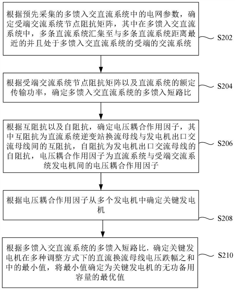
[0020] According to this embodiment, an embodiment of a method for determining the optimal value of the reactive power reserve capacity of a generator is also provided. It should be noted that the steps shown in the flow chart of the accompanying drawings can be executed in a set of computer-executable instructions such as and, although a logical order is shown in the flowcharts, in some cases the steps shown or described may be performed in an order different from that shown or described herein.

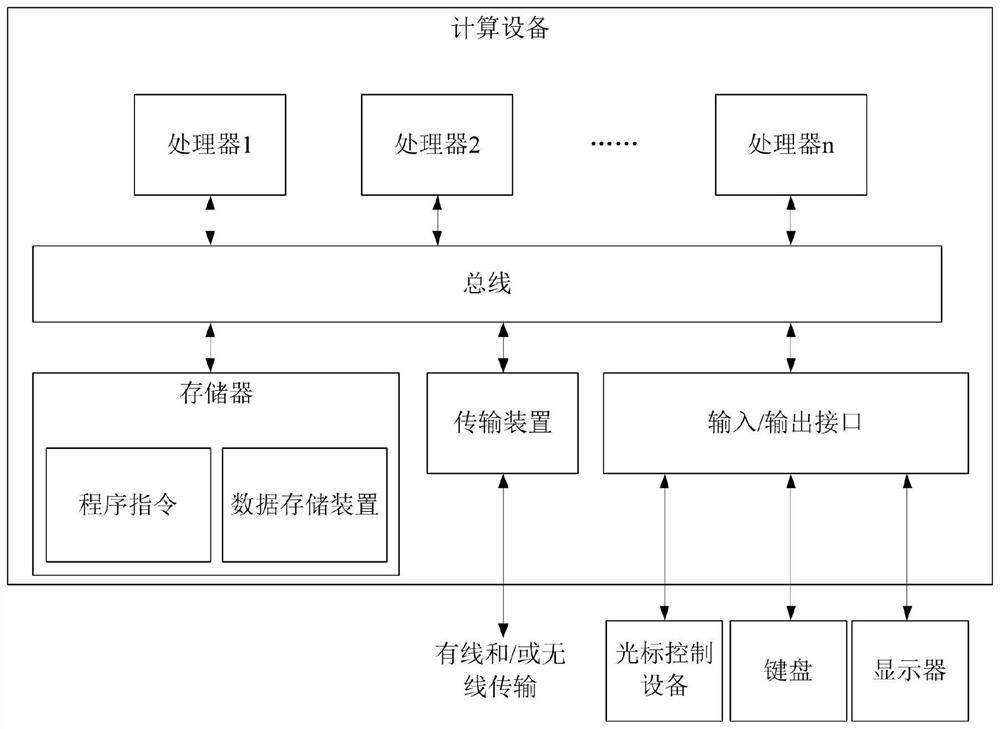
[0021] The method embodiments provided in this embodiment can be executed in a server or similar computing devices. figure 1 A block diagram of a hardware structure of a computing device for implementing a method for determining an optimal value of a reactive power reserve capacity of a generator is shown. Such as figure 1 As shown, the computing device may include one or more processors (processors may include but not limited to processing devices such as microprocessors MCUs or p...

Embodiment 2

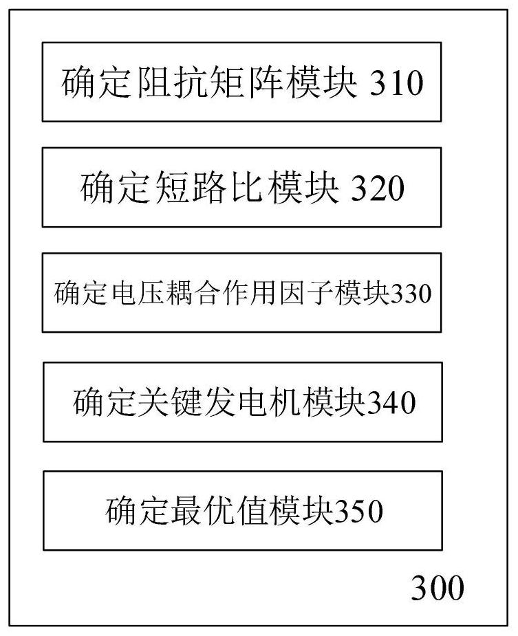
[0057] image 3 A device 300 for determining the optimal value of the reactive power reserve capacity of a generator according to this embodiment is shown, and the device 300 corresponds to the method according to the first aspect of Embodiment 1. refer to image 3 As shown, the device 300 includes: an impedance matrix determination module 310, configured to determine the receiving-end AC system node impedance matrix according to the pre-collected grid parameters in the multi-infeed AC-DC system, wherein in the multi-infeed AC-DC system, The multiple DC systems are collected to the AC system closest to the multiple DC systems and at the receiving end of the multi-infeed AC / DC system; the short circuit ratio module 320 is used to determine the short circuit ratio module 320 according to the node impedance matrix of the receiving end AC system and the rated transmission of the DC system Power, determine the multi-infeed short-circuit ratio of the multi-infeed AC-DC system; dete...

Embodiment 3

[0065] Figure 4 A device 400 for determining the optimal value of the reactive power reserve capacity of a generator according to this embodiment is shown, and the device 400 corresponds to the method according to the first aspect of Embodiment 1. refer to Figure 4As shown, the device 400 includes: a processor 410; and a memory 420, connected to the processor 410, for providing the processor 410 with instructions for processing the following processing steps: according to the grid parameters in the multi-feed AC / DC system collected in advance , to determine the node impedance matrix of the AC system at the receiving end, where in the multi-infeed AC-DC system, multiple DC systems converge to the AC system closest to the multiple DC systems and at the receiving end of the multi-infeed AC-DC system; according to the received Determine the multi-infeed short-circuit ratio of the multi-infeed AC-DC system based on the node impedance matrix of the terminal AC system and the rate...


PUM


Abstract

The invention discloses a method and device for determining the optimal value of the reactive standby capacity of a generator. The method comprises the steps of determining a node impedance matrix ofa receiving end alternating current system according to pre-collected power grid parameters in a multi-infeed alternating current and direct current system, and in the multi-infeed alternating currentand direct current system, gathering a plurality of direct current systems to an alternating current system which is closest to the direct current systems and located at the receiving end of the multi-infeed alternating current and direct current system; determining a multi-infeed short-circuit ratio of a multi-infeed AC / DC system according to the node impedance matrix of a receiving end AC system and the rated transmission power of a DC system; determining a voltage coupling effect factor according to the mutual impedance and the self-impedance; determining a key generator from the pluralityof generators according to the voltage coupling effect factor; and determining the minimum value of the sum of the DC converter bus voltage drop amplitudes of the key generator in various adjustmentmodes, and determining the minimum value as the optimal value of the reactive standby capacity of the key generator.

Description

technical field [0001] The present application relates to the technical field of power systems, in particular to a method and device for determining the optimal value of the reactive power reserve capacity of a generator. Background technique [0002] The basic national conditions of uneven distribution of energy resources and productivity determine the inevitability of large-scale cross-regional flow of energy and electricity in my country. HVDC transmission technology has been widely used in long-distance and large-capacity transmission and large-scale power grid interconnection due to its transmission distance not limited by the stability of synchronous operation and large transmission capacity. In recent years, a large number of DC projects have been put into operation in my country, and multiple DC transmission systems have been placed on the same AC grid at close distances in multiple load centers, that is, multiple feed-in DC transmission systems. However, as the pro...

Claims


Application Information

Patent Timeline
IPC IPC(8): G06Q10/04G06Q10/06G06Q50/06
CPCG06Q10/04G06Q10/0631G06Q50/06
Inventor 邵瑶徐旖旎吴鸣季宇李蕊熊雄张海刘海涛
Owner STATE GRID SHANGHAI ENERGY INTERCONNECTION RES INST CO LTD
Learn More