
Athermalization laser emission lens

A laser emission, athermalization technology, applied in optics, optical components, instruments, etc., can solve problems such as the decrease of ranging ability or damage ability, and increase the control accuracy of the focusing structure, so as to reduce the motion accuracy and control accuracy, reduce Motion accuracy and control accuracy requirements, the effect of less material

Pending Publication Date: 2020-12-25
XI'AN INST OF OPTICS & FINE MECHANICS - CHINESE ACAD OF SCI
View PDF0 Cites 0 Cited by
  • Summary
  • Abstract
  • Description
  • Claims
  • Application Information

AI Technical Summary

Problems solved by technology

[0004] In order to solve the technical problems that the existing laser emitting system is more sensitive to the ambient temperature, resulting in a decline in ranging capability or damage capability, and increasing the control accuracy of the focusing structure during distance focusing, the present invention provides an athermalized laser emitting lens

Method used


Image

  • Athermalization laser emission lens
  • Athermalization laser emission lens
  • Athermalization laser emission lens

Examples


Embodiment Construction

[0033] The content of the present invention will be further described in detail below in conjunction with the accompanying drawings and specific embodiments.

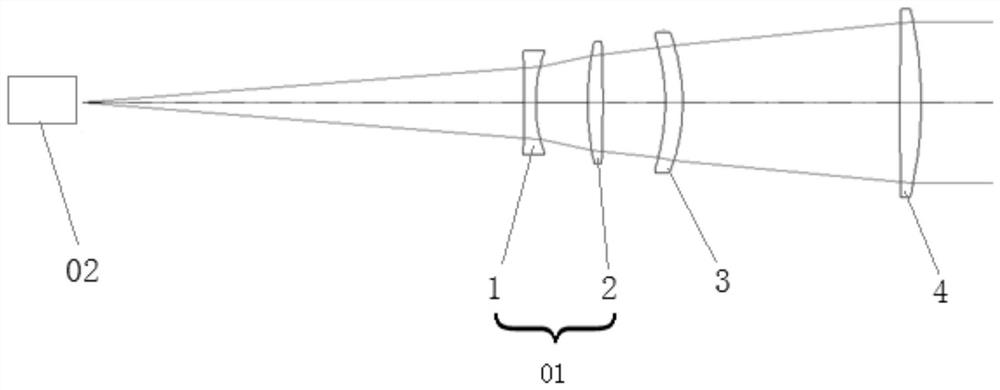
[0034] Such as figure 1 As shown, an athermalized laser emitting lens includes an optical system located on the outgoing light path of the laser 02. The optical system adopts a four-separated transmission structure. The optical system includes a fixed mirror group 01 arranged coaxially along the outgoing beam direction of the laser 02. , the third lens 3 and the fourth lens 4; the fixed lens group 01 includes the first lens 1 and the second lens 2 which are coaxially arranged in sequence along the light transmission direction, the first lens 1 is a biconcave lens with negative refractive power, and the second The lens 2 is a double-convex lens with positive refractive power; the third lens 3 is a meniscus lens with positive refractive power bent toward the side of the laser 02; the fourth lens 4 is a double-convex lens ...


PUM

PropertyMeasurementUnit
thicknessaaaaaaaaaa
thicknessaaaaaaaaaa
thicknessaaaaaaaaaa

Abstract

The invention belongs to the field of laser ranging, and provides an athermalization laser emission optical lens. The lens solves the problems that an existing laser emission system is sensitive to the environment temperature, so the ranging capacity or damage capacity is reduced, and during distance focusing, the control precision of a focusing structure is increased. The lens comprises a first lens body, a second lens body, a third lens body and a fourth lens body which are sequentially and coaxially arranged; the first lens body, the second lens body, the third lens body and the fourth lensbody are respectively a biconcave lens body with negative focal power, a biconvex lens body with positive focal power, a meniscus lens body with positive focal power and bent to the side of a laser,and a biconvex lens body with positive focal power; the first lens body and the fourth lens body are made of quartz silica glass; the second lens body and the third lens body are made of crown flint H-FK61 glass; and the third lens body can move back and forth along the direction of an optical axis to realize laser emission lens focal plane offset compensation under different operating distances.The lens is provided with only four lenses body, the two materials of quartz silica glass and crown flint H-FK61 glass are used in pairs, and athermalization design of the system is achieved in the whole distance focusing range.

Description

technical field [0001] The invention belongs to the field of laser ranging, and relates to a laser emitting lens, in particular to an athermalized laser emitting lens. Background technique [0002] With the continuous development of optoelectronic equipment in the field of low-altitude defense, real-time laser ranging or laser damage is required, and the laser emission system needs to be integrated on the airborne or vehicle. Therefore, the laser emission system also needs to adapt to the airborne or vehicle environment. One of the key factors is temperature adaptability. [0003] Existing laser emission systems generally have a narrow range of wavelengths, and a single glass material or two glass materials are usually used in the design. The system’s heat dissipation capability is poor, which makes the system more sensitive to temperature changes. In order to adapt to temperature changes, real-time Adjusting the focus greatly reduces the ranging capability or damage effect...

Claims


Application Information

Patent Timeline
Patent Type & Authority Applications(China)
IPC IPC(8): G02B15/14G02B1/00G02B15/15
CPCG02B15/143507G02B1/00G02B15/15
Inventor 刘凯姜凯闫佩佩单秋莎李哲周亮
Owner XI'AN INST OF OPTICS & FINE MECHANICS - CHINESE ACAD OF SCI
Learn More