Micro-lens device and manufacturing method thereof

A micro-lens, transparent technology, applied in lens, optics, instruments, etc., can solve the problems of limited use of molds, damage to molds and plastic plates, and high cost of mold opening

Inactive Publication Date: 2020-12-25
陈梓林
View PDF10 Cites 0 Cited by
  • Summary
  • Abstract
  • Description
  • Claims
  • Application Information

AI Technical Summary

Problems solved by technology

[0003] At present, this kind of microlens is generally formed by pressing a hard mold on a transparent plastic plate. The mold needs to be equipped with a plurality of microlens molds very accurately, and the cost of mold opening is very high. The plate will be damaged due to contact, and the number of times the mold can be used is also limited
Therefore, the manufacturing cost of this type of microlens device is difficult to reduce at present

Method used


Image

  • Micro-lens device and manufacturing method thereof
  • Micro-lens device and manufacturing method thereof
  • Micro-lens device and manufacturing method thereof

Examples


Embodiment 1

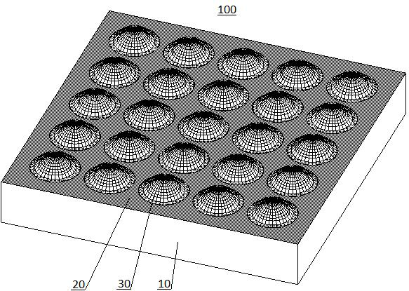
[0031] The microlens device 100 includes a transparent glass substrate 10 with a thickness of 0.4 mm. One surface of the transparent glass substrate 10 is provided with a shielding layer 20 and a microlens array composed of a large number of microlens units 30 .

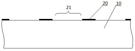
[0032] The shielding layer 20 is a patterned black photosensitive resin layer (light transmittance less than 10%), which forms a large number of circular light-transmitting windows 21 through patterning of yellow light processes such as exposure and development, and the light-transmitting windows 21 are located in each microlens unit 30 bottom.

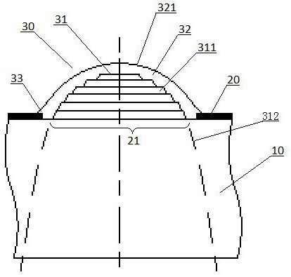
[0033] The micro-lens unit 30 is disposed on each light-transmitting window 21 , which is a micro-convex lens with a diameter less than 0.2 mm. Each microlens unit 30 includes a transparent support portion 31 and a smooth portion 32. The support portion 31 is formed by overlapping circular transparent resin sheets 311 with the same refractive index. The thickness of the resi...

Embodiment 2

[0043] On the basis of Embodiment 1, the support part is changed to be formed by overlapping a plurality of strip-shaped resin sheets 311', and the width of the resin sheet 311' decreases layer by layer according to the negative parabolic function relationship from bottom to top, thus forming The microlens device 100' includes a plurality of microlens units 30' having lenticular functions, which constitutes the second embodiment of the present invention.

Embodiment 3

[0045] On the basis of the second embodiment, the width of the resin sheet 311' is changed from bottom to top to decrease layer by layer according to a linear function relationship, and thus the formed microlens device 100" includes a plurality of microlens units 30" with prism functions , then constitute the third embodiment of the present invention.


PUM

PropertyMeasurementUnit
sizeaaaaaaaaaa
thicknessaaaaaaaaaa
thicknessaaaaaaaaaa

Abstract

The invention provides a micro-lens device. The micro-lens device comprises a transparent substrate and a micro-lens unit which is arranged on the transparent substrate; the micro-lens unit comprisesa transparent support part and a smooth part; the support part is formed by overlapping multiple layers of miniature transparent resin sheets which are consistent in refractive index; and the smooth part covers the support part and is provided with a smooth surface formed by infiltration of a fluid on the support part. The micro-lens device does not need to be formed by mold pressing on a plasticplate, and the manufacturing cost of the micro-lens device is reduced. The invention further provides a manufacturing method of the micro-lens device.

Description

technical field [0001] The invention relates to a microlens device and a manufacturing method thereof, belonging to the technical field of optical lenses. Background technique [0002] A microlens generally refers to an optical lens whose characteristic size (such as diameter and width, the same below) is less than 1mm, especially less than 0.2mm. A microlens device made by arranging a large number of microlenses on a lens substrate can be used in arrayed optical sensors, arrayed light emitting devices, and other devices, and has very high application value. [0003] At present, this kind of microlens is generally formed by pressing a hard mold on a transparent plastic plate. The mold needs to be equipped with a plurality of microlens molds very accurately, and the cost of mold opening is very high. The board will be damaged due to contact, and the number of times the mold can be used is also limited. Therefore, it is difficult to reduce the manufacturing cost of this type...

Claims


Application Information

Patent Timeline
Patent Type & Authority Applications(China)
IPC IPC(8): G02B3/00
CPCG02B3/0006G02B3/0012
Inventor 陈梓林
Owner 陈梓林
Why Eureka
Try Eureka