
Food processing dryer

A food processing and drying machine technology, applied in the direction of drying machines, drying, heating devices, etc., to achieve the effect of avoiding uneven drying and uniform drying effect

Inactive Publication Date: 2020-12-25
广州佳优华信息科技有限公司
View PDF0 Cites 1 Cited by
  • Summary
  • Abstract
  • Description
  • Claims
  • Application Information

AI Technical Summary

Problems solved by technology

[0005] In order to solve the above-mentioned technology, when the bean food is dried by a dryer, the hot air flow generated by the dryer can only flow and skip the surface layer of the bean food, and the bean food located in a deeper place cannot be directly contacted. Hot air currents, resulting in only the more superficial legumes being dried when drying piles of legumes

Method used


Image

  • Food processing dryer
  • Food processing dryer
  • Food processing dryer

Examples


Embodiment 1

[0027] as attached figure 1 to attach Figure 5 Shown:

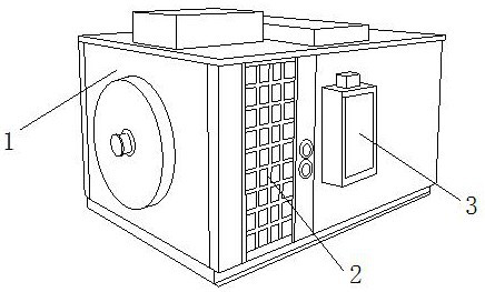
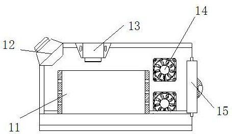
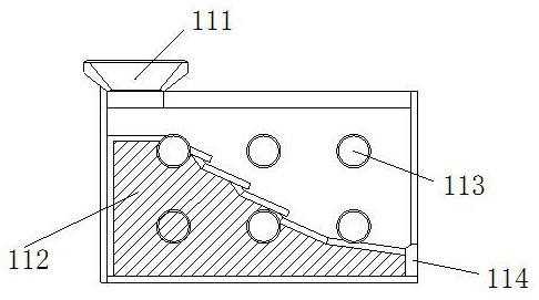
[0028] The invention provides a food processing dryer, the structure of which includes a drying chamber 1, an air outlet 2, and an electric box 3. The outer end surface of the drying chamber 1 is embedded with an electric box 3, and the air outlet 2 is embedded Located on the outer end face of the drying bin 1, the electric box 3 is embedded and installed on the right side of the air outlet 2, and the drying bin 1 includes a storage bin 11, a material inlet 12, a heating machine 13, and a blower 14 1. The hatch 15, the storage bin 11 is embedded and installed directly under the heating machine 13, the feeding port 12 is connected to the upper left side of the drying bin 1 by welding, and the heating machine 13 is embedded and engaged Installed above the left side of the blower 14, the blower 14 is symmetrically installed on the upper and lower sides of the inner end of the drying bin 1, and the hatch door 15 is inlaid ...

Embodiment 2

[0035] as attached Image 6to attach Figure 8 As shown: the partition block 121 includes a toggle ring 211, a flow groove 212, a blocking block 213, a movable rod 214, and a movable mechanism 215. The groove 212 is inlaid on the inner end surface of the partition block 121, the barrier block 213 is evenly inlaid and installed on the outer surface of the upper end of the toggle ring 211, the movable rod 214 is movably engaged and installed directly above the movable mechanism 215, the movable The mechanism 215 is embedded and installed above the inner side of the partition block 121 , and the inner end surface of the flow tank 212 is provided with a groove with the same diameter as the blocking block 213 for the blocking block 213 to slide up and down.

[0036] Wherein, the movable mechanism 215 includes a rotating disk 151, a connecting rod 152, a centrifugal wheel 153, a movable block 154, and a limit ring 155. The rotating disk 151 is inlaid and engaged with the connecting...


PUM


Abstract

The invention discloses a food processing dryer. The food processing dryer structurally comprises a drying bin, an air outlet and an electric box; the electric box is fixedly installed on the end faceof the outer side of the drying bin in an embedded mode; the air outlet is formed in the end face of the outer side of the drying bin in an embedded mode; the electric box is fixedly installed at theright side of the air outlet in an embedded mode; due to the fact that collecting grooves and penetration holes are formed in the outer end face of a leakage mechanism, part of bean food flows downwards to an interlayer between separation blocks along the inner contour of the leakage mechanism when the bean food falls downwards to the moment, and due to the fact that the interlayer between the separation blocks is longitudinally arranged, the bean food can be effectively dried when airflow flows towards a separation mechanism in the middle along ventilation openings in the left side and the right side; and the problem of uneven drying is avoided.

Description

technical field [0001] The invention belongs to the field of food processing, and more specifically relates to a food processing dryer. Background technique [0002] The food processing dryer is a kind of machine that uses a hot-melt machine and a blower to pass the air through the hot-melt machine. After heating, the hot air flows in the equipment, and the water stains on the food surface are dried after the hot air flows through the food surface. Dry. [0003] Based on the discovery of the above inventors, the existing methods mainly have the following deficiencies, such as: when using a dryer to dry beans, the hot air flow produced by the dryer can only flow over the surface of the beans layer, and the bean food located in the deep part cannot directly contact the hot air flow, so when drying piles of bean food, only the bean plants on the relatively surface can be dried. [0004] Therefore need to propose a kind of food processing dryer. Contents of the invention ...

Claims


Application Information

Patent Timeline
IPC IPC(8): F26B17/12F26B21/00F26B23/00F26B25/00F26B25/04
CPCF26B17/12F26B21/001F26B23/00F26B25/00F26B25/04
Inventor 刘少洁
Owner 广州佳优华信息科技有限公司
Learn More