Rotational flow air floatation separation device and system

A technology of swirling air flotation and separation device, which can be used in oil/oily substance/float removal device, centrifugal separation water/sewage treatment, flotation water/sewage treatment, etc., and can solve the problem of low recycling rate

Pending Publication Date: 2020-12-25
CHONGQING NAIDE MACHINERY EQUIP
View PDF0 Cites 0 Cited by
  • Summary
  • Abstract
  • Description
  • Claims
  • Application Information

AI Technical Summary

Problems solved by technology

[0005] Aiming at the deficiencies in the prior art, the present invention provides a cyclone air flotation separation device and system to solve the technical problem of low reuse rate of traditional oily wastewater treatment in the related art

Method used


Image

  • Rotational flow air floatation separation device and system
  • Rotational flow air floatation separation device and system

Examples


Embodiment Construction

[0034] In order to make the purpose, technical solutions and beneficial effects of the present invention more clear, the technical solutions in the present invention will be further described below in conjunction with the accompanying drawings and embodiments. It should be understood that the specific embodiments described here are only used to explain the present invention, not to limit the present invention.

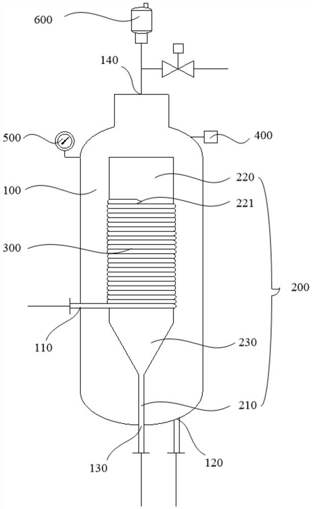
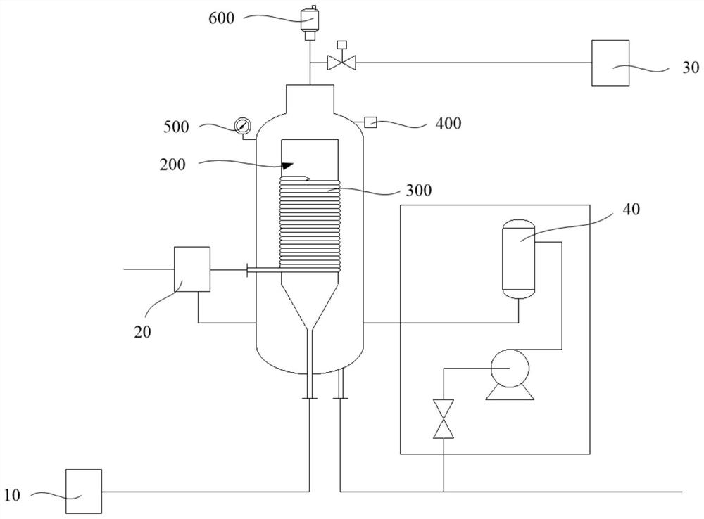
[0035] see figure 1 with figure 2 , the invention provides a cyclone air flotation separation device, comprising:

[0036] The separation chamber 100 has an accommodating space; the separation chamber 100 has a mixed gas-liquid entry position 110, a clean water outflow position 120 and a sludge discharge position 130;

[0037] The swirl chamber 200 is arranged in the separation chamber 100 and is located in the accommodating space; the swirl chamber 200 includes a first communication pipe 210 passing through the sludge discharge position 130 Connected to the sludge...


PUM

PropertyMeasurementUnit
diameteraaaaaaaaaa
diameteraaaaaaaaaa

Abstract

The invention provides a rotational flow air floatation separation device and system. The device comprises a separation chamber which is provided with an accommodation space; a separation chamber is provided with a mixed gas-liquid inlet position, a clear water outlet position and a sludge discharge position; a rotational flow chamber is arranged in the separation chamber and is positioned in theaccommodating space; the rotational flow chamber comprises a first communicating pipe, and the first communicating pipe penetrates through the sludge discharge position to be communicated with a sludge recovery device; the rotational flow chamber is provided with an open top end and a rotational flow access position; the coil pipe is wound and overlapped outside the rotational flow chamber; one end of the coil pipe penetrates through the mixed gas-liquid inlet position to be communicated with an oily wastewater mixed gas-liquid device, and the other end of the coil pipe is tangentially communicated with the rotational flow access position; the clear water outflow position is communicated with a micro-nano bubble generator, and the other end of the micro-nano bubble generator is communicated with an oily wastewater mixed gas-liquid device. By optimizing the structure of the rotational flow air floatation separation device, the technical problem that the traditional oily wastewater treatment reutilization rate is low is solved.

Description

technical field [0001] The invention relates to the technical field of water treatment, in particular to a cyclone air flotation separation device and system. Background technique [0002] Oily wastewater refers to wastewater containing a relatively high concentration of oily organic matter. If it is discharged directly, it will cause serious pollution and eutrophication of the water body, causing the destruction of biological chains such as aquatic plants, microorganisms, and algae, and seriously damaging the structure of the water body. At present, the treatment of oily wastewater mainly includes four categories of methods: one is the physical method mainly based on centrifugal separation method, coarse granulation method and membrane separation method; the other is chemical method mainly based on chemical oxidation method and photochemical method The third is physical and chemical methods based on flotation, adsorption, and magnetic adsorption separation methods; the four...

Claims


Application Information

Patent Timeline
Patent Type & Authority Applications(China)
IPC IPC(8): C02F9/02C02F101/30
CPCC02F1/24C02F1/38C02F1/40C02F9/00C02F2101/30C02F2201/002C02F2209/03C02F2209/42C02F2303/14C02F2303/26
Inventor 陈明翠盘章俊梁伦硕姚海军
Owner CHONGQING NAIDE MACHINERY EQUIP
Why Eureka
Try Eureka