Auxiliary transportation equipment for glass production
A technology of auxiliary transportation and equipment, which is applied in the field of auxiliary transportation equipment for glass production, can solve problems such as glass breakage, glass slipping, and damage, and achieve the effect of avoiding glass slipping and damage and saving manpower
- Summary
- Abstract
- Description
- Claims
- Application Information
AI Technical Summary
Problems solved by technology
Method used
Image
Examples
Embodiment 1
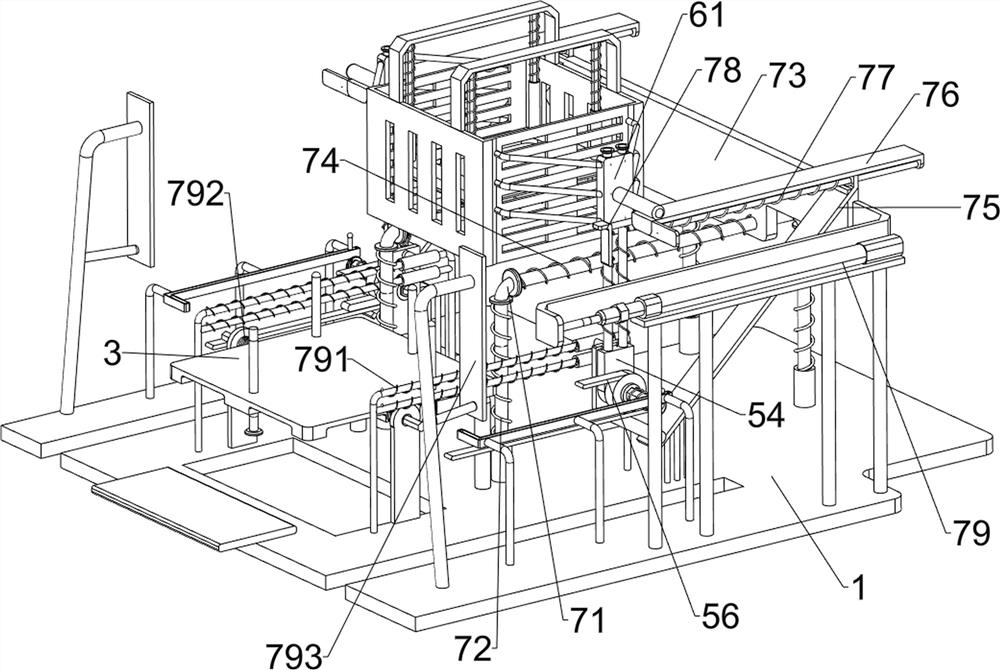
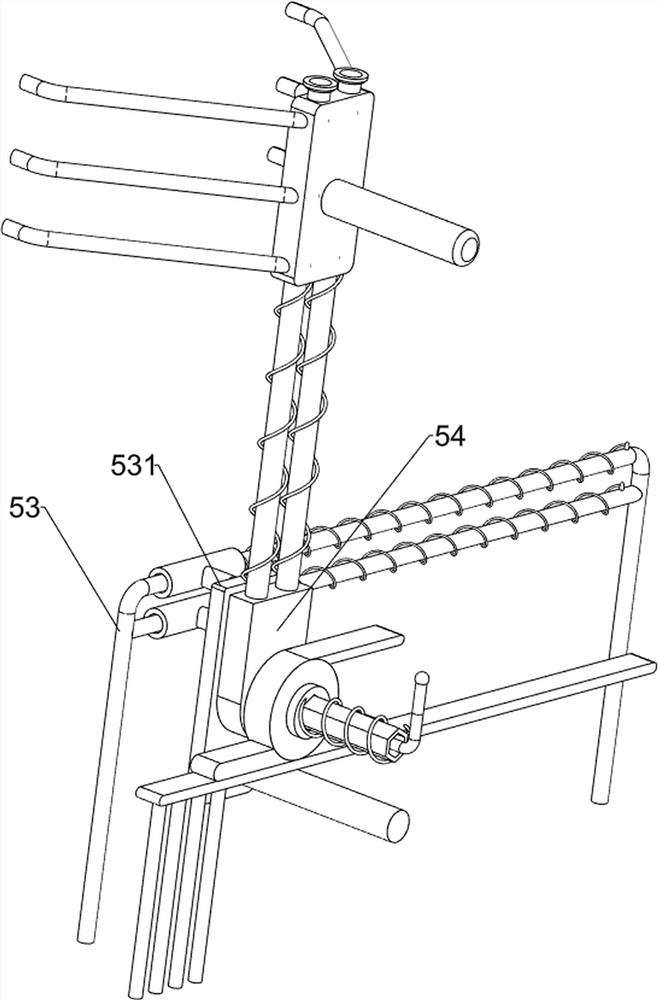
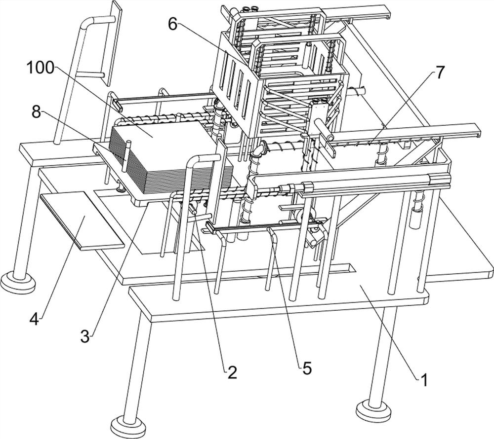
[0024] An auxiliary transportation equipment for glass production, such as figure 1 , 2 As shown in and 4, it includes a support 1, a rhombus rod 2, a placement plate 3 and a fixed plate 4. The top left side of the support 1 is rotationally connected with a rhombus rod 2, and the rhombus rod 2 is connected with a placement plate 3, and the placement plate 3 The part on the right side of the rhombus bar 2 is longer than the part on the left side of the rhombus bar 2, the part of the placement plate 3 on the right side of the rhombus bar 2 is supported by the support 1, and the top left side of the support 1 is connected with a fixed plate 4, which also includes There are a moving assembly 5 and a frame assembly 6 , the support 1 is provided with the mobile assembly 5 , and the mobile assembly 5 is provided with the frame assembly 6 .
[0025] The moving assembly 5 includes a guide frame 51, a limiting plate 52, a guide rail 53, a sliding plate 531, a slider 54, an inner diamon...
Embodiment 2
[0029] On the basis of Example 1, such as image 3As shown, the extruding assembly 7 is also included, and the extruding assembly 7 includes a slide rail 71, a second compression spring 72, a slide plate 73, a first return spring 74, a swash plate 75, a sliding frame 76, a first common spring 77, The second connecting plate 78, the cylinder 79, the second return spring 791, the torsion spring 792 and the second contact plate 793, the front and rear sides of the top of the support 1 are slidably connected with slide rails 71, between the slide rail 71 and the support 1 A second compression spring 72 is connected, a slide plate 73 is slidably connected between the slide rails 71 on both sides, a first return spring 74 is connected between the slide plate 73 and the slide rail 71, and a slant plate 75 is connected to the front and rear sides of the slide plate 73. The slant plate 75 cooperates with the slide block 54, the slant plate 75 is slidably connected with a sliding frame ...
Embodiment 3
[0032] On the basis of Example 2, such as figure 2 As shown, it also includes a limit assembly 8, the limit assembly 8 includes a first slide bar 81, a second slide bar 82 and a second ordinary spring 83, and the placement plate 3 is slidably connected with three first slide bars 81, three The first slide bar 81 is distributed in a triangular shape, the second common spring 83 is connected between the first slide bar 81 and the placement plate 3, and the left side of the placement plate 3 is slidingly connected with the second slide bar 82, and the second slide bar 82 is connected with the There is a certain frictional force between the placing boards 3 .
[0033] When placing the glass, you can first pull the second slide bar 82 to move downward, then the user can place the glass on the placement plate 3 and limit the position through the first slide bar 81. After placing the glass, you can push the second slide bar 82 reset and cooperate with the first slide bar 81 to limi...
PUM
 Abstract
Description
Claims
Application Information
 - R&D
- Intellectual Property
- Life Sciences
- Materials
- Tech Scout
- Unparalleled Data Quality
- Higher Quality Content
- 60% Fewer Hallucinations
Browse by: Latest US Patents, China's latest patents, Technical Efficacy Thesaurus, Application Domain, Technology Topic, Popular Technical Reports.
© 2025 PatSnap. All rights reserved.Legal|Privacy policy|Modern Slavery Act Transparency Statement|Sitemap|About US| Contact US: help@patsnap.com


