Forming method of split tool composite material support

A molding method and tooling technology, which is applied in the field of molding of split tooling composite brackets, to achieve the effect of accurate direction, uniform and controlled pressure transmission

Active Publication Date: 2020-12-25
BEIJING SATELLITE MFG FACTORY
View PDF11 Cites 2 Cited by
  • Summary
  • Abstract
  • Description
  • Claims
  • Application Information

AI Technical Summary

Problems solved by technology

[0005] The technical problem solved by the present invention is: to overcome the deficiencies of the prior art, to provide a forming method for split tooling composite brackets, to solve the problems of difficult demoulding of traditional semi-enclosed cavity brackets in narrow spaces, and insufficient pressure sensing at corners

Method used


Image

  • Forming method of split tool composite material support
  • Forming method of split tool composite material support
  • Forming method of split tool composite material support

Examples


Embodiment Construction

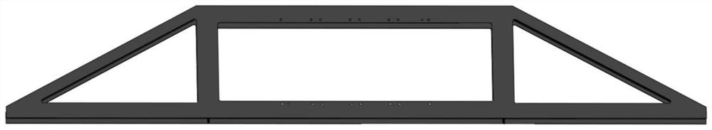
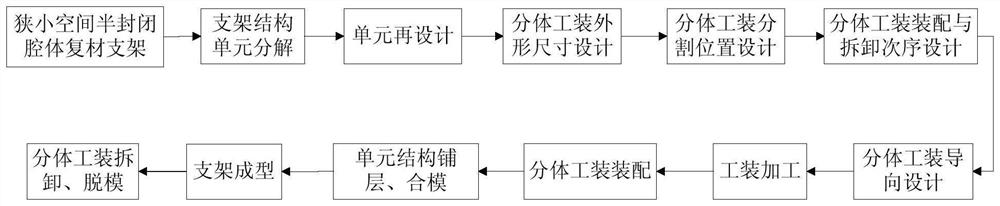
[0038]Such asfigure 1 As shown, the carrier of the present invention is a narrow space semi-closed cavity composite bracket, and its molding process is as followsfigure 2 Shown.

[0039]Step 1: Redesign the structure size of the element blank according to the size of the support structure (element division). Two triangular elements and one rectangular element can be divided. The decomposition line is in the middle of the vertical beam of the I-beam section. The element section after decomposition is Type C;

[0040]Step 2: Design the soft film according to the triangular unit and the rectangular unit. The cross-section of the soft film is C-shaped, and the shape is consistent with the shape of the inner cavity of the unit, and the thickness is generally 5mm. The function of the soft membrane is to evenly transmit pressure and at the same time serve as the benchmark for composite material paving;

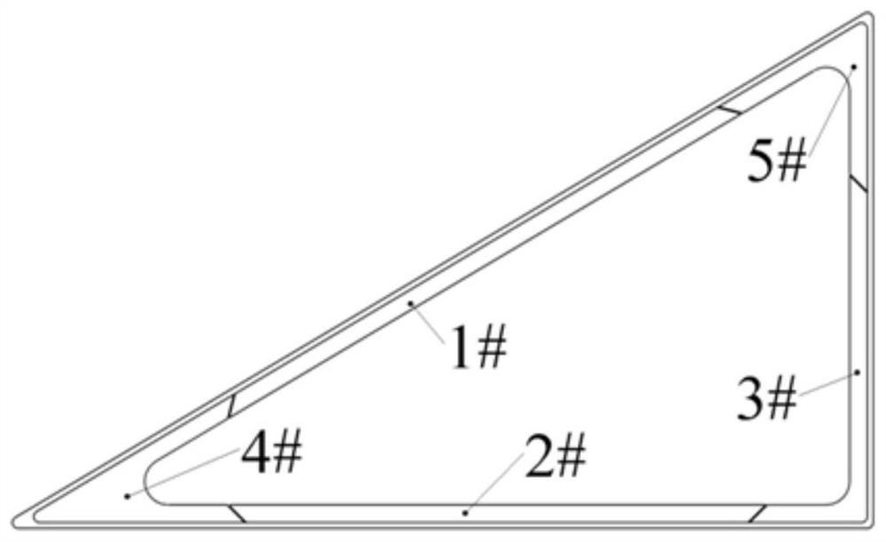
[0041]Step 3: Design triangular and rectangular split tooling (such asimage 3 withFigure 4 (Sho...


PUM


Abstract

The invention discloses a forming method of a split tool composite material support. The forming method comprises the following steps that (1) a support structure is decomposed into units; (2) the decomposed units are redesigned; (3) the boundary dimension of a split tool is designed; (4) the segmentation position of the split tool is designed; (5) the disassembling sequence of the split tool is determined, wherein the assembling sequence is opposite to the disassembling sequence; (6) the guide design of the split tool is performed; (7) a movable split tool with guiding is machined and manufactured; (8) the split tool is assembled according to the specified assembling sequence, and installing into a soft film is performed; (9) layer laying and mold closing of the unit structures are performed; (10) a small-space I-shaped beam section composite material support is formed; (11) a vacuum bag film, a pressure equalizing plate, outer frame connecting screws, an outer frame, a mounting guidepin and a curing bottom plate are removed one by one; and the split tool is disassembled according to the specified disassembling sequence.

Description

Technical field[0001]The invention relates to a method for forming a split tooling composite bracket. It is suitable for forming composite brackets with semi-enclosed cavities in narrow spaces on camera bracket components in remote sensing and space stations.Background technique[0002]In order to meet the requirements of mechanics and load connection, a number of semi-closed, small-space unit structures are designed on the camera bracket component. These closed or semi-closed unit structures put forward higher requirements on the molding technology. There are two ways to form the traditional stent unit. One is to use vacuum bag film to pressurize, but in the unit stent, especially the corners, the pressure is often not in place, which eventually leads to product delamination, localized high glue content, Defects such as unqualified flaw detection; second, the metal forming tooling is designed inside the bracket, and the product is pressurized by the thermal expansion of the metal, bu...

Claims


Application Information

Patent Timeline
Patent Type & Authority Applications(China)
IPC IPC(8): B29C70/34B29C70/38B29C70/54
CPCB29C70/342B29C70/382B29C70/386B29C70/54Y02T50/40
Inventor 徐鹤徐伟丽陶积柏郑建虎张玉生陈维强刘佳王洋李莺歌董丰路白刚董薇
Owner BEIJING SATELLITE MFG FACTORY
Why Eureka
Try Eureka