
Full-automatic trimming and stamping equipment for hardware wire box

A fully automatic technology for edge trimming and punching, applied in the field of hardware, can solve problems such as low hole opening efficiency

Inactive Publication Date: 2020-12-25
赵鹏生
View PDF0 Cites 6 Cited by
  • Summary
  • Abstract
  • Description
  • Claims
  • Application Information

AI Technical Summary

Problems solved by technology

[0005] In order to overcome the problems in home decoration, the metal wire box is one of the electrical accessories, because the wires used for decoration pass through the wire tube, and the junction box is used as a transition at the joint of the wire, and the wire tube is connected to the metal wire box. , the wires in the wire tube are connected in the metal wire box to protect the wires and connect the wires. The existing cutting method of the metal wire box burrs is to manually use the upper and lower punching knives to cut off. When using the punching knife for cutting work, Only one side of the wire box can be cut off at a time. When cutting off the waste burrs on other sides, it is necessary to manually turn over the wire box again and repeat the above operations, and cut back and forth four times to complete the removal of the waste burrs of the wire box. After the cutting is completed, it is necessary to punch the wire holes on the four sides of the wire box that has removed the waste burr. At present, the method of opening the wire holes of the wire box is to manually use a punching machine to do the hole work, and the punching machine can only punch one side at a time. wire holes, which leads to the disadvantage of low hole opening efficiency. The technical problem of the present invention is to provide a fully automatic edge trimming and punching equipment for hardware wire boxes

Method used


Image

  • Full-automatic trimming and stamping equipment for hardware wire box
  • Full-automatic trimming and stamping equipment for hardware wire box
  • Full-automatic trimming and stamping equipment for hardware wire box

Examples


Embodiment 1

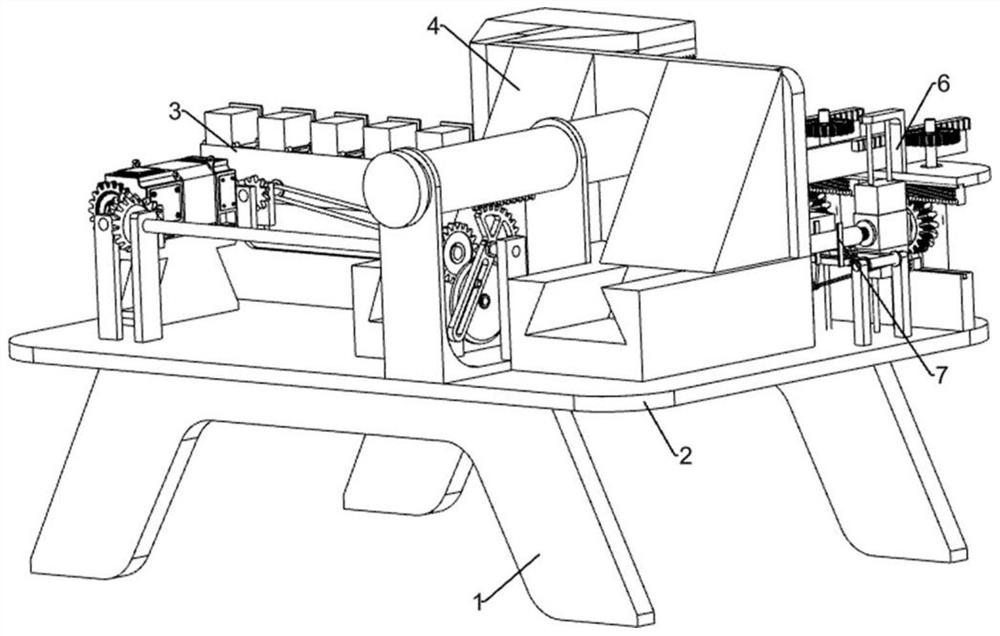
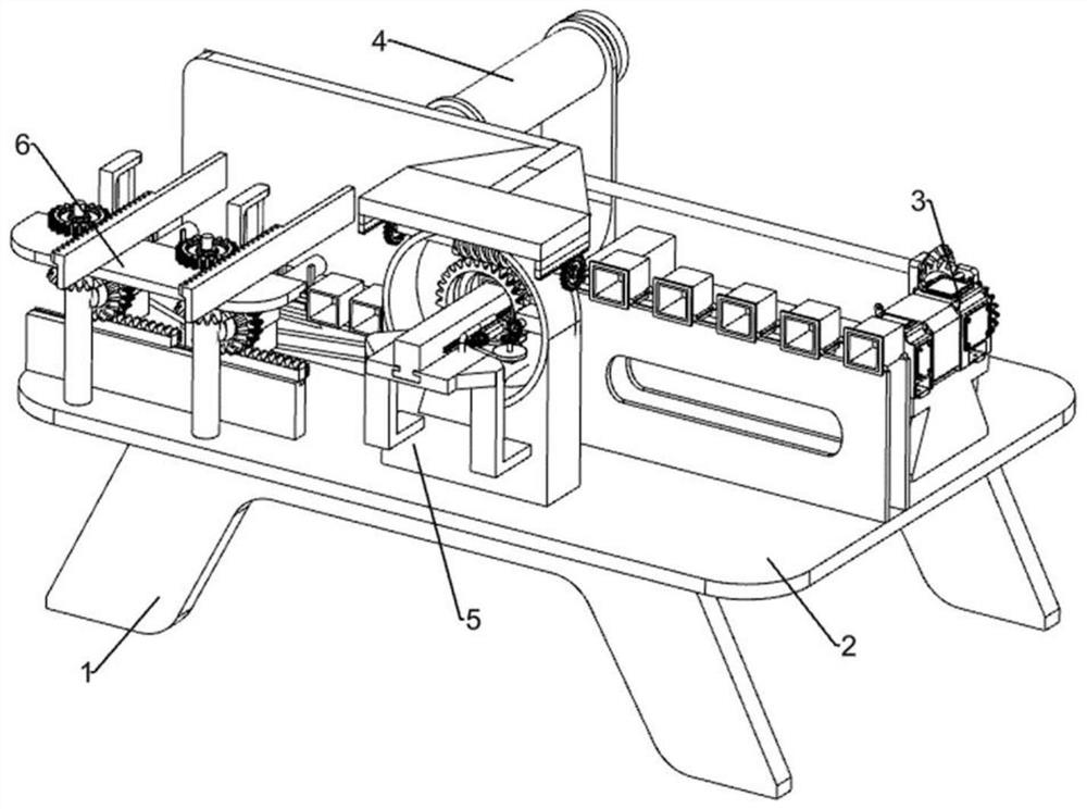
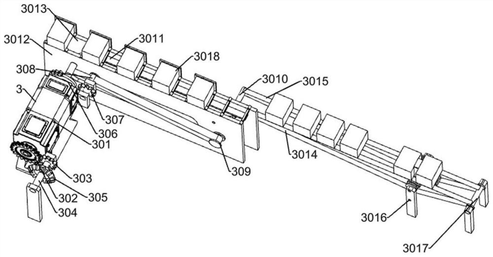
[0032] A metal wire box automatic edge trimming and punching equipment, such as Figure 1-10 As shown, it includes a chassis 1, a machine board 2, a transmission mechanism 3, an auxiliary mechanism 4, a burr cutting mechanism block 5, a punching mechanism 6 and a stop frame 7; the upper end of the chassis 1 is fixed on the machine board 2; the machine board 2 One side of the upper end is fixed to the transmission mechanism 3; the middle part of the upper end of the machine board 2 is fixed to the burr cutting mechanism block 5; the other side of the upper end of the machine board 2 is fixed to the auxiliary mechanism 4 and the punching mechanism 6, and the auxiliary mechanism 4 is connected by transmission The punching mechanism 6 and the auxiliary mechanism 4 are connected to the burr cutting mechanism block 5;

[0033] When the device is in use, first place the device at the place of use, then power on the external control panel, and then start the internal power of the devi...


PUM


Abstract

The invention relates to the field of hardware, in particular to full-automatic trimming and stamping equipment for a hardware wire box. The full-automatic trimming and stamping equipment for the hardware wire box is provided . According to the technical implementation solution, the full-automatic trimming and stamping equipment for the hardware wire box comprises a bottom frame, a machine plate,a conveying mechanism, an auxiliary mechanism, a burr cutting mechanism block and the like, wherein the upper end of the bottom frame is fixedly connected to the machine plate, and one side of the upper end of the machine plate is fixedly connected to the conveying mechanism. According to the full-automatic trimming and stamping equipment for the hardware wire box, the effects that an upper stamping knife and a lower stamping knife which are used for replacing manual work are used for cutting off the hardware wire box, the four edges of the hardware wire box can be cut off at the same time, therefore the working efficiency is improved, and meanwhile when the device is used for stamping, wire holes in the two side faces can be stamped at the same time, and the perforating efficiency is improved.

Description

technical field [0001] The invention relates to the field of hardware, in particular to a fully automatic trimming and punching equipment for hardware wire boxes. Background technique [0002] The hardware box is a kind of junction box, and it is also an electrical material commonly used in electrical decoration. [0003] In home decoration, the metal wire box is one of the electrical accessories, because the wires used for decoration pass through the wire tube, and the junction box is used as a transition at the joint of the wire. The wire tube is connected to the metal wire box. The wires inside the tube are connected in the hardware wire box to protect the wires and connect the wires. The existing cutting method of the metal wire box is to manually use the upper and lower punching knives to cut off. When using the punching knife for cutting work, each Only one side of the wire box can be cut off. When cutting off the waste edges of other sides, it is necessary to manuall...

Claims


Application Information

Patent Timeline
IPC IPC(8): B21D28/34B21D28/28B21D43/02B21D43/12B21D43/14B21D43/18B23D31/00B23D33/02B23D33/00B23P23/04B23Q5/04
CPCB21D28/28B21D28/34B21D43/026B21D43/027B21D43/12B21D43/145B21D43/18B23D31/00B23D33/00B23D33/02B23P23/04B23Q5/04
Inventor 赵鹏生
Owner 赵鹏生
Learn More