
Gas pressure maintaining and flow dividing device and method for inflation drilling

A technology of inflatable drilling and flow diversion device, which is applied in earthwork drilling, wellbore flushing, wellbore/well components, etc. It can solve the problems of increased operation risk, poor rock-carrying effect, and easy formation of gas columns, etc., and achieves no corrosion The effect of blocking risk, improving operation efficiency, and reducing operation risk

Pending Publication Date: 2020-12-22
BC P INC CHINA NAT PETROLEUM CORP +1
View PDF0 Cites 0 Cited by
  • Summary
  • Abstract
  • Description
  • Claims
  • Application Information

AI Technical Summary

Problems solved by technology

[0004] The purpose of the present invention is to overcome the above-mentioned deficiencies in the prior art, to provide a gas pressure maintaining and diverting device and method for inflatable drilling, which overcomes the problem that the output gas volume of the gas supply equipment supporting the inflatable underbalanced drilling in the prior art cannot be fixed according to The demand adjustment causes the gas supply volume to be greater than the demanded gas volume during aerated underbalanced drilling, and there are problems such as large negative pressure difference in the well, uneven gas-liquid mixing, and easy formation of gas columns, which lead to circulation interruption, wellbore instability, and rock-carrying effect In the event of deterioration and leakage, the risk of well control is high, and the blowout potential of the return outlet is large, which may lead to complex problems or hidden dangers such as safety hazards, which will reduce the efficiency of drilling operations and increase operational risks. Problems with gas pressure maintaining and diverting devices

Method used


Image

  • Gas pressure maintaining and flow dividing device and method for inflation drilling
  • Gas pressure maintaining and flow dividing device and method for inflation drilling
  • Gas pressure maintaining and flow dividing device and method for inflation drilling

Examples


specific Embodiment approach

[0035] It should be noted that the structures, proportions, sizes, etc. shown in this specification are only used to match the content disclosed in the specification, for those who are familiar with this technology to understand and read, and are not used to limit the conditions for the implementation of the present invention. Any modification of structure, change of proportional relationship or adjustment of size shall still fall within the scope covered by the technical contents disclosed in the present invention without affecting the functions and objectives of the present invention.

[0036] At the same time, terms such as "upper", "lower", "left", "right", "middle" and "one" quoted in this specification are only for the convenience of description and are not used to limit this specification. The practicable scope of the invention and the change or adjustment of its relative relationship shall also be regarded as the practicable scope of the present invention without any su...

Embodiment 1

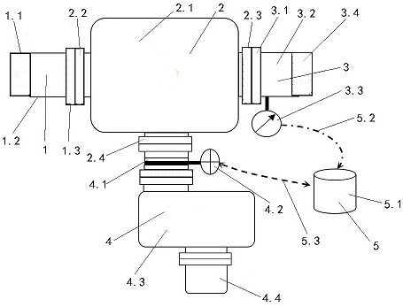
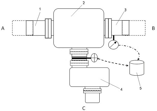
[0038] Such as Figure 1~2 As shown, the present invention discloses a gas pressure maintaining and diverting device for inflatable drilling, including an air intake pipeline 1, a buffer chamber 2, a gas supply pipeline 3, a flow diversion assembly 4 and a flow diversion control assembly 5, the air intake pipeline 1 The inlet end is connected to the main gas supply line A for inflatable drilling, the outlet end of the air intake pipeline 1 is connected to the inlet end of the buffer chamber 2, the outlet end of the buffer chamber 2 is connected to the inlet end of the gas supply pipeline 3, and the outlet end of the gas supply pipeline 3 is connected to the inlet end of the gas supply pipeline 3. The gas control skid B is connected, the outlet end of the buffer chamber 2 is also connected with the inlet end of the flow diversion assembly 4, the outlet end of the flow separation assembly 4 is placed at the grit chamber C, and the gas supply pipeline 3 and the flow distribution a...

Embodiment 2

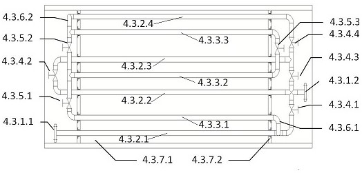
[0040] Such as Figure 1~2 As shown, preferably, the split flow assembly 4 includes a split flow control valve 4.1, a split flow control valve control assembly 4.2, a split flow friction unit 4.3 and an exhaust pipeline 4.4, and the inlet port of the split flow control valve 4.1 is connected to the buffer chamber 2 through a flange. The outlet end is connected, the outlet end of the diversion control valve 4.1 is connected to the inlet end of the diversion friction unit 4.3, the outlet end of the diversion friction unit 4.3 is connected to the exhaust pipeline 4.4, and the outlet end of the exhaust pipeline 4.4 is placed at the grit chamber C, the The diversion control valve control component 4.2 is installed on the diversion control valve 4.1 for controlling the opening degree of the diversion control valve 4.1, and the diversion control valve control component 4.2 is electrically connected with the diversion control component 5 .

[0041] The split flow assembly 4 can change...


PUM


Abstract

The invention discloses a gas pressure maintaining and flow dividing device and method for inflation drilling. The gas pressure maintaining and flow dividing device comprises a gas inlet pipeline (1),a buffer cavity (2), a gas supply pipeline (3), a flow dividing assembly (4) and a flow dividing control assembly (5), the inlet end of the gas inlet pipeline (1) is connected with an inflation drilling gas supply main pipeline (A), the outlet end of the gas inlet pipeline (1) is connected with the buffer cavity (2), the outlet end of the buffer cavity (2) is connected with the inlet end of the gas supply pipeline (3), the outlet end of the gas supply pipeline (3) is connected with a gas control pry (B) for inflation drilling, the outlet end of the buffer cavity (2) is further connected withthe inlet end of the flow dividing assembly (4), the outlet end of the flow dividing assembly (4) is placed at a riffling tank (C), and the gas supply pipeline (3) and the flow dividing assembly (4) are correspondingly and electrically connected with the flow dividing control assembly (5).

Description

technical field [0001] The invention belongs to the technical field of gas supply for pneumatic drilling, and in particular relates to a gas pressure maintaining and diverting device and method for pneumatic drilling. Background technique [0002] Air-filled drilling, air-filled foam drilling and gas drilling belong to the category of air-filled underbalanced drilling. During drilling, gas is injected into the drilling fluid in the wellbore to form gas-containing drilling fluid or foam drilling fluid, or pure gas is injected into the wellbore as the drilling circulation medium, thereby reducing Bottomhole pressure to achieve the purpose of leak prevention and reservoir protection. [0003] However, the output gas volume of the gas supply equipment for aerated underbalanced drilling is fixed and cannot be adjusted according to demand, resulting in the gas supply volume being greater than the demanded gas volume during aerated underbalanced drilling, resulting in large negativ...

Claims


Application Information

Patent Timeline
IPC IPC(8): E21B21/16E21B21/14E21B21/08E21B21/10
CPCE21B21/16E21B21/14E21B21/08E21B21/106
Inventor 杨赟韦海防王培峰赵航博李晓黎李婧杨敏张弢陈宁姜生辉赵文庄邓凯白钰仵磊陈鹏伟欧勇赵胜斌常加彪海照新
Owner BC P INC CHINA NAT PETROLEUM CORP
Learn More