
Convenient-to-position metal stamping part for bridge and positioning and mounting method

A metal stamping part, positioning and installation technology, applied in the field of metal stamping parts, can solve problems such as affecting the progress of the project, the guardrail cannot be assembled smoothly, etc., to achieve the effect of easy installation and positioning

Inactive Publication Date: 2020-12-22
陈烁
View PDF0 Cites 2 Cited by
  • Summary
  • Abstract
  • Description
  • Claims
  • Application Information

AI Technical Summary

Problems solved by technology

The metal guardrail is usually composed of stamping parts such as pillars and guardrails fixed on the bridge. The traditional pillars are usually fixed on the bridge with bolts, and then the guardrail is fixed between the two pillars; The distance between the two pillars is required to be relatively precise. If the installation distance between the two pillars is not accurately positioned and installed, the guardrail between the two pillars will not be able to be assembled smoothly, and the pillars will need to be re-installed and adjusted, which will affect the progress of the project; therefore There is a need for a metal stamping part for a bridge that is convenient for positioning and a positioning installation method to solve the above problems

Method used


Image

  • Convenient-to-position metal stamping part for bridge and positioning and mounting method
  • Convenient-to-position metal stamping part for bridge and positioning and mounting method
  • Convenient-to-position metal stamping part for bridge and positioning and mounting method

Examples


Embodiment Construction

[0026] The following will clearly and completely describe the technical solutions in the embodiments of the present invention with reference to the accompanying drawings in the embodiments of the present invention. Obviously, the described embodiments are only some, not all, embodiments of the present invention. Based on the embodiments of the present invention, all other embodiments obtained by persons of ordinary skill in the art without making creative efforts belong to the protection scope of the present invention.

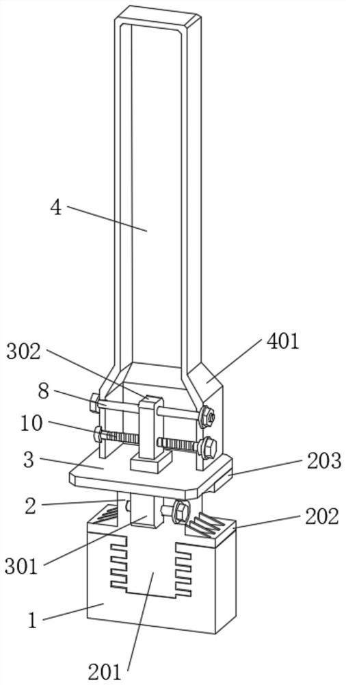
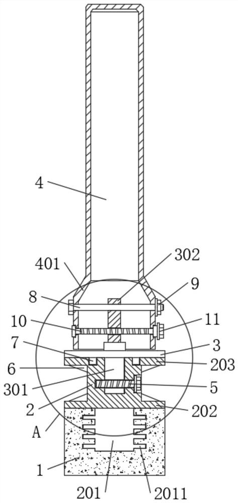
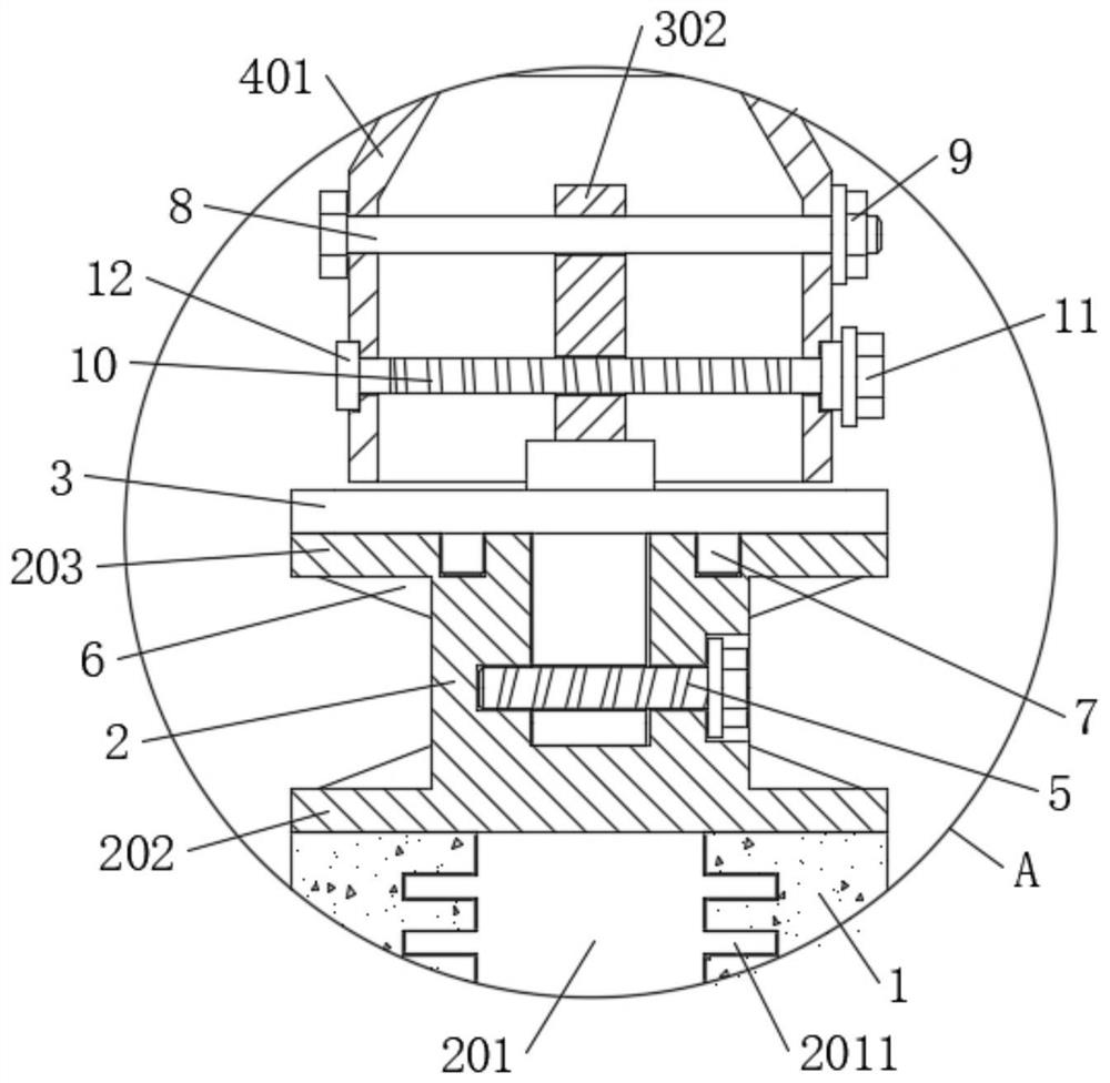
[0027] The present invention provides such Figure 1-4 A metal stamping part for a bridge that is convenient for positioning and a positioning installation method are shown, including a bridge concrete base 1, a fixed base 2, a connecting seat 3 and a pillar 4, the bridge concrete base 1 is connected with a fixed base 2, and the fixed base 2 is connected with a connecting seat 3, and the connecting seat 3 is connected with the adjusting box seat 401 at the bot...


PUM


Abstract

The invention discloses a convenient-to-position metal stamping part for a bridge and a positioning and mounting method. The convenient-to-position metal stamping part comprises a bridge concrete base, a fixed base, a connecting seat and supporting columns, the bridge concrete base is connected with the fixed base, the fixed base is connected with the connecting seat, and the connecting seat is connected with adjusting box seats at the bottoms of the supporting columns; a screw rod is rotatably connected between the two side walls of each adjusting box seat, adapter clamping rings are arrangedat the two ends of each screw rod and clamped on the outer wall of the corresponding adjusting box seat, the screw rods are in threaded connection with the middle of the connecting seat, a hexagonalwrench head is arranged at one end of each screw rod, and a guardrail is arranged between every two adjacent supporting columns; and a first magnetic sensor and a second magnetic sensor which are usedfor positioning the distance between every two adjacent adjusting box seats are correspondingly attracted to the hexagonal wrench heads of the two adjacent adjusting box seats in a magnetic manner. When a cross beam protective guard is installed, the distance between the two supporting columns can be finely adjusted, and mounting and positioning of the cross beam protective guard are facilitated.

Description

technical field [0001] The invention relates to the field of metal stamping parts, in particular to a conveniently positioned metal stamping part for a bridge and a positioning and installation method. Background technique [0002] In the process of bridge construction, it is usually necessary to build metal fences on both sides of the bridge for protection. The metal guardrail is usually composed of stamping parts such as pillars and guardrails fixed on the bridge. The traditional pillars are usually fixed on the bridge with bolts, and then the guardrail is fixed between the two pillars; The distance between the two pillars is required to be relatively precise. If the installation distance between the two pillars is not accurately positioned and installed, the guardrail between the two pillars will not be able to be assembled smoothly, and the pillars will need to be re-installed and adjusted, which will affect the progress of the project; therefore There is a need for a m...

Claims


Application Information

Patent Timeline
Patent Type & Authority Applications(China)
IPC IPC(8): E01D19/00E01D19/10E01D21/00E01D101/30
CPCE01D19/00E01D19/103E01D21/00E01D2101/30
Inventor 陈烁
Owner 陈烁
Learn More