
Protective solar cell panel mounting structure

A solar panel and installation structure technology, which is applied to the support structure of photovoltaic modules, photovoltaic power generation, electrical components, etc. Conversion efficiency and other issues, to achieve the effect of enhancing utilization, ensuring light transmittance, and good protection effect

Inactive Publication Date: 2020-12-18
阳光中科(福建)能源股份有限公司
View PDF0 Cites 1 Cited by
  • Summary
  • Abstract
  • Description
  • Claims
  • Application Information

AI Technical Summary

Problems solved by technology

[0004] The purpose of the present invention is: in order to solve the existing deficiencies in the use of the existing protective structure for installing solar panels, not only the solar panels are easily corroded by harmful substances such as rainwater and dust, but also easily damaged by high altitude. The impact of falling objects, flying stones and other impact objects, and the dust on the surface of the solar panel can easily affect its light conversion efficiency, and most of the heat emitted by the solar panel is directly discharged into the air, and this heat energy cannot be recycled. , resulting in the waste of resources, and a protective solar panel installation structure proposed

Method used


Image

  • Protective solar cell panel mounting structure
  • Protective solar cell panel mounting structure
  • Protective solar cell panel mounting structure

Examples


Embodiment Construction

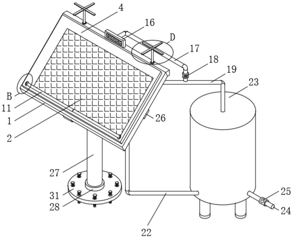
[0044] The technical solutions in the embodiments of the present invention will be clearly and completely described below with reference to the accompanying drawings in the embodiments of the present invention. Obviously, the described embodiments are only a part of the embodiments of the present invention, but not all of the embodiments. Based on the embodiments of the present invention, all other embodiments obtained by those of ordinary skill in the art without creative efforts shall fall within the protection scope of the present invention.

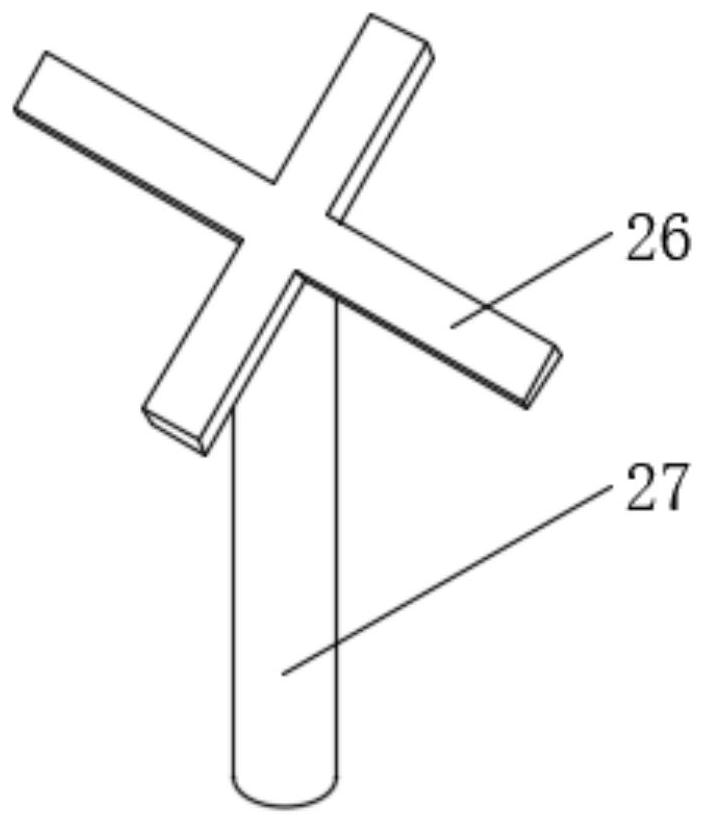
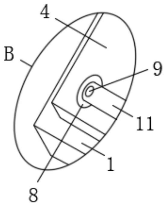
[0045] see Figure 1-13 , the present invention provides a technical solution: a protective solar panel mounting structure, including a solar panel mounting seat 1 and an intelligent control system 38 arranged on one side of the solar panel mounting seat 1, the solar panel mounting seat 1 A solar panel 2 is embedded in the inner side, and a limit slot 3 is set on the top of the solar panel mount 1 corresponding to the periphery of the...


PUM


Abstract

The invention discloses a protective solar cell panel mounting structure, which belongs to the technical field of solar cell panels, and comprises a solar cell panel mounting seat and an intelligent control system arranged at one side of the solar cell panel mounting seat, and is characterized in that the inner side of the solar cell panel mounting seat is connected with a solar cell panel in an embedded manner; a limiting groove is formed in the top, corresponding to the periphery of the solar cell panel, of the solar cell panel mounting base, and a light-transmitting cover is sleeved with the limiting groove. According to the invention, through the mutual cooperation of the designed light-transmitting cover, an elastic supporting device, a windshield wiper, a first motor, a second motor,fan blades, an electromagnetic valve, a heat conductor water storage box, a photosensitive sensor, a microcontroller and a rotating speed sensor, heat energy is recycled, the utilization rate of solar energy can be further enhanced, the utilization rate of solar energy is improved, the stress area is erduced, not only can a large amount of flying sand be prevented from impacting the light-transmitting cover in a large area, but also the supporting load of the base can be prevented from being increased due to a large stress surface.

Description

technical field [0001] The invention belongs to the technical field of solar cell panels, and in particular relates to a protective solar cell panel mounting structure. Background technique [0002] Solar panels are devices that directly or indirectly convert solar radiation into electrical energy through the photoelectric effect or photochemical effect by absorbing sunlight. Its universal use still has certain limitations. Compared with ordinary batteries and rechargeable batteries, solar cells are more energy-saving and environmentally friendly green products. [0003] The cost of solar panels is relatively high. In order to ensure the normal and safe operation of solar panels, many protective structures are usually added to the installation structure of solar panels. There are still some deficiencies in the solar panel, not only is it easy to cause the solar panel to be corroded by harmful substances such as rain and dust, but also easily hit by impact objects such as fa...

Claims


Application Information

Patent Timeline
Patent Type & Authority Applications(China)
IPC IPC(8): H02S20/32H02S40/10H02S40/20H02S40/42
CPCH02S20/32H02S40/10H02S40/20H02S40/425Y02E10/50
Inventor 柯雨馨梁兴芳王惠群戴亮亮
Owner 阳光中科(福建)能源股份有限公司
Learn More