
Clamp type inertia piezoelectric linear motor

A linear motor and clamp-type technology, applied in the direction of piezoelectric effect/electrostrictive or magnetostrictive motors, generators/motors, electrical components, etc., can solve problems such as difficult to bear working loads and small thrusts, and achieve Increased output thrust, simple structure, and high-precision effects

Active Publication Date: 2020-12-18
NANJING INST OF TECH
View PDF7 Cites 1 Cited by
  • Summary
  • Abstract
  • Description
  • Claims
  • Application Information

AI Technical Summary

Problems solved by technology

However, the current performance of this type of motor has constraints: although the motor has high precision, its thrust is small and it is difficult to withstand the working load

Method used


Image

  • Clamp type inertia piezoelectric linear motor
  • Clamp type inertia piezoelectric linear motor
  • Clamp type inertia piezoelectric linear motor

Examples


Embodiment Construction

[0023] Embodiments of the present invention will be described in further detail below in conjunction with the accompanying drawings.

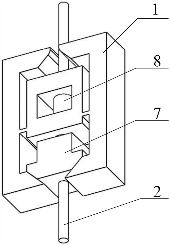
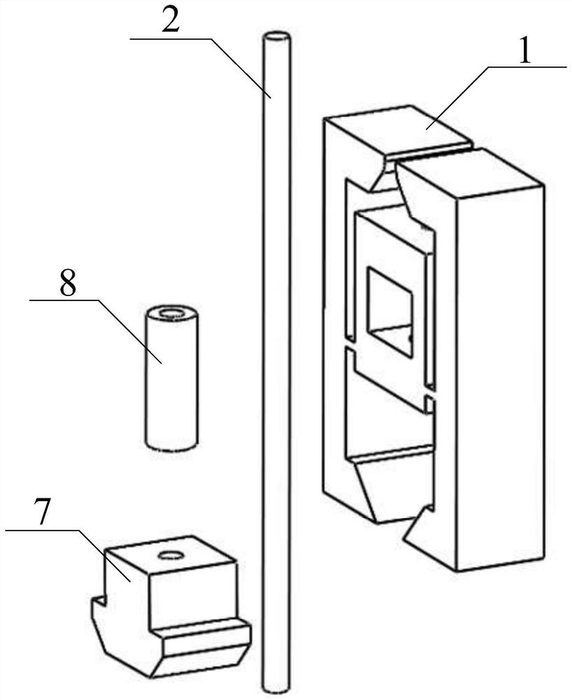
[0024] like figure 1 As shown, the present invention is a clamp-type inertial piezoelectric linear motor, including a stator fixed frame 1 and an output rod 2, the stator fixed frame 1 is a hollow structure, and the two ends of the stator fixed frame 1 are respectively connected to the left lever 3 And the right lever 4, the upper and lower ends of the left lever 3 and the right lever 4 are respectively horizontally provided with an upper clamp block 5 and a lower clamp block 6, and a wedge 7 is placed between the two lower clamp blocks 6;

[0025] The stator fixed frame 1 is provided with an annular laminated piezoelectric ceramic 8, the upper end of the annular laminated piezoelectric ceramic 8 is against the inner surface of the upper end of the stator fixed frame 1, and the annular laminated piezoelectric ceramic 8 The lower end abuts agai...


PUM


Abstract

The invention discloses a clamp type inertia piezoelectric linear motor. The clamp type inertia piezoelectric linear motor comprises a stator fixing frame and an output rod, the stator fixing frame isof a hollow structure, the two ends of the stator fixing frame are connected with a left lever and a right lever respectively, the upper ends and the lower ends of the left lever and the right leverare horizontally provided with an upper clamp block and a lower clamp block respectively, and a wedge block is placed between the two lower clamp blocks; annular laminated piezoelectric ceramic is arranged in the stator fixing frame, the upper end of the annular laminated piezoelectric ceramic abuts against the inner surface of the upper end of the stator fixing frame, the lower end of the annularlaminated piezoelectric ceramic abuts against the upper end of the wedge block, the output rod sequentially penetrates through the stator fixing frame, the annular laminated piezoelectric ceramic andthe wedge block downwards, and the lower end of the output rod extends out of the wedge block. According to the inertia piezoelectric linear motor, the stator adopts a clamp type structure, the leftlever and the right lever can be adjusted, and different precision requirements are met; and meanwhile, the clamp type structure can improve the output thrust by increasing the positive pressure and the friction force between the clamp and the output rod during working while realizing high precision.

Description

technical field [0001] The invention belongs to the technical field of piezoelectric precision actuation, and in particular relates to a clamp-type inertial piezoelectric linear motor. Background technique [0002] Piezoelectric linear motors have the characteristics of high positioning accuracy, fast response speed, flexible design, and immunity to electromagnetic interference. They have broad application prospects in emerging cutting-edge technology fields. In recent years, piezoelectric linear motors have been developed rapidly under the extensive attention of researchers from many countries. Classified according to the principle, the piezoelectric motor can be divided into resonant and non-resonant motors. In the resonant motor, the vibrating body is driven by a signal in the ultrasonic frequency band to generate micro-amplitude vibration through modal coupling, and the dynamic force is driven by friction. The motor produces a large-stroke motion, and the use of the cou...

Claims


Application Information

Patent Timeline
Patent Type & Authority Applications(China)
IPC IPC(8): H02N2/02H02N2/04
CPCH02N2/025H02N2/04
Inventor 孙梦馨王寅冯勇黄卫清
Owner NANJING INST OF TECH
Learn More