
Offshore wind plant arrangement structure and arrangement method

A technology for arranging structures and wind farms, applied in wind power generation, circuit devices, electrical components, etc., can solve the problems of many landing electrical submarine cable loops, many landing electrical loops, and few electrical submarine cable loops, etc., to reduce the sea area And sea airspace space, saving sea area and sea airspace space, the effect of less electrical circuits

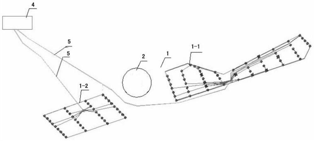
Pending Publication Date: 2020-12-18
CHINA ENERGY ENG GRP GUANGDONG ELECTRIC POWER DESIGN INST CO LTD
View PDF0 Cites 3 Cited by
  • Summary
  • Abstract
  • Description
  • Claims
  • Application Information

AI Technical Summary

Problems solved by technology

[0004] One of the purposes of the present invention is to provide an offshore wind farm layout structure with electrical Outstanding substantive features and significant progress such as fewer submarine cable loops, small sea area, low project cost, and reduced environmental pollution
[0005] The second object of the present invention is to provide a layout method for offshore wind farms, which has the advantages of less electrical circuits, Outstanding substantive features and significant progress such as small sea area, low project cost, and reduced environmental pollution

Method used


Image

  • Offshore wind plant arrangement structure and arrangement method
  • Offshore wind plant arrangement structure and arrangement method
  • Offshore wind plant arrangement structure and arrangement method

Examples


specific Embodiment 1

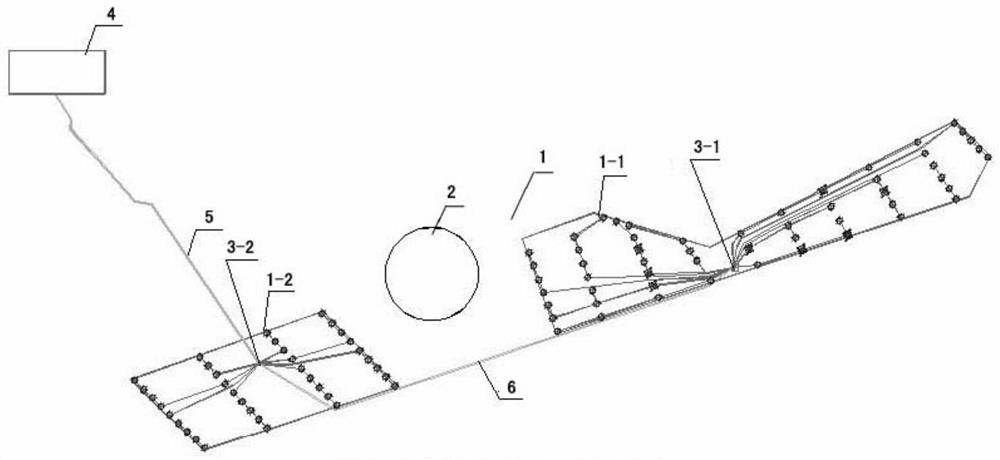
[0033] refer to figure 1 , the offshore wind farm layout structure involved in the specific embodiment 1 of the present invention includes an offshore wind farm 1, the offshore wind farm 1 is divided into several block wind farms by an offshore separation area 2, and an offshore wind farm is set in each block wind farm. Booster station, the power generation output of each wind farm in each block is connected to the power input of the offshore booster station in the wind farm in the block, forming a booster structure for the power generation of each wind farm in each block; the power output of each offshore booster station The terminals are connected (connected together) through submarine cables, and the offshore booster station in one of the block wind farms that is closer to the land is provided with an output terminal of land transmission power to form the output terminal of land transmission power of offshore wind farm 1. A set of landing cables connects the output end of ...

specific Embodiment 2

[0046] The characteristics of the specific embodiment 2 of the present invention are: the offshore wind farm 1 is divided into the south block wind farm and the north block wind farm by the offshore separation area 2, and the South China Sea booster station is arranged in the south block wind farm, The wind farm in the block is equipped with a Beihai step-up station, and the power output terminal of the wind farm in the south block is connected to the power input end of the step-up station in the South China Sea to form a power step-up structure for the wind farm in the south block; the wind power station in the north block The power generation output of the wind farm is connected to the power input of the North Sea booster station to form the power generation boost structure of the wind farm in the northern block; the power output terminals of the South and North Sea booster stations are connected through submarine cables. The offshore booster station in a nearby block wind fa...

specific Embodiment 3

[0048] The characteristics of the specific embodiment 3 of the present invention are: the offshore wind farm 1 is divided into four block wind farms in the east, south, west and north by the offshore separation area 2, and an offshore booster station is arranged in each block wind farm. The power generation output of each block wind farm is connected to the power input of the offshore booster station in the block wind farm to form a boost structure for the power generation of each block wind farm; the power output of each offshore booster station is connected through a submarine cable. connected (connected together), the offshore booster station in one of the block wind farms that is closer to the land is provided with the output terminal of the land transmission power to form the output terminal of the land transmission power of the offshore wind farm 1. The output end of the land-transmission electricity is connected with the electricity input end of the onshore centralized c...


PUM


Abstract

The invention relates to an offshore wind power plant arrangement structure and an arrangement method. The offshore wind power plant arrangement structure comprises an offshore wind power plant whichis divided into a plurality of block wind power plants by offshore separation areas, and the offshore wind power plant arrangement structure is characterized in that an offshore booster station is arranged in each block wind power plant; a power generation quantity output end of each block wind power plant is connected with an electric quantity input end of the offshore booster station in the block wind power plant to form a power generation quantity boosting structure of each block wind power plant; the electric quantity output ends of all the offshore booster stations are connected togetherthrough submarine cables, and the offshore booster station in one block wind power plant close to the land is provided with a land transmission electric quantity output end to form a land transmissionelectric quantity output end of the offshore wind power plant 1. And the land transmission electric quantity output end is connected with the electric quantity input end of a land centralized controlcenter through a group of landing cables to form a simplified structure type offshore wind power plant arrangement structure. The offshore wind power plant arrangement structure has the characteristics and improvements of few electrical loops, small sea area, low project cost, environmental pollution reduction and the like.

Description

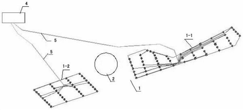
technical field [0001] The invention relates to an arrangement structure and an arrangement method of an offshore wind farm. It belongs to the technical field of distributed power supply method. Background technique [0002] Offshore wind farms are generally arranged in a complete sea area, but when they are divided into two or more areas by anchorages or other marine protected areas (hereinafter referred to as separation areas), it is necessary to choose the overall layout that is both in line with the plan and the most economical. Program. [0003] In the prior art, when the complete offshore wind farm is divided into two independent offshore wind farms in the east and west by the middle separation area, the respective landing methods are usually adopted: one is to pull a group of offshore cables from the wind farm in the east (each group Offshore cables (including two offshore cables) bypass the anchorage from the seabed to the vicinity of the wind farm in the west area...

Claims


Application Information

Patent Timeline
Patent Type & Authority Applications(China)
IPC IPC(8): H02J3/38
CPCH02J3/381H02J2300/28Y02E10/76
Inventor 郑伯兴李伟科钱萍范用春王鹏李陈飞
Owner CHINA ENERGY ENG GRP GUANGDONG ELECTRIC POWER DESIGN INST CO LTD
Learn More