Direct-current emergency transfer box and using method thereof
A transfer box and direct current technology, which is applied in the direction of direct current circuits with more than three wires, parallel operation of direct current power supplies, direct current network circuit devices, etc., can solve the problems of lack of effective supervision and protection, increased danger of direct current boxes, uneven quality, etc. problems, to achieve the effect of improving reliability and safety, improving on-site work efficiency, and improving safety
- Summary
- Abstract
- Description
- Claims
- Application Information
AI Technical Summary
Problems solved by technology
Method used
Image
Examples
Embodiment 1
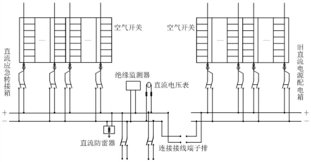
[0045] Such as figure 1 As shown, a DC emergency transfer box 2 of the present invention includes a monitoring and protection device, and the monitoring and protection device includes an insulation monitor connected in parallel at the positive and negative poles of the DC emergency transfer box 2 power supply bus, a DC monitor and a DC lightning protection The insulation monitor performs real-time insulation monitoring on the DC emergency transfer box 2 circuit. The DC monitor has the functions of DC measurement, display and undervoltage alarm and control (contact output), and displays the measured DC voltage in real time. The undervoltage can be set at will Alarm voltage, and relay contact output; real-time monitoring of the working voltage of the DC emergency transfer box 2 circuit, when the circuit voltage is abnormal or DC grounding, an alarm signal is sent; the DC lightning protection device prevents the instantaneous The overvoltage is limited within the voltage range th...
Embodiment 2
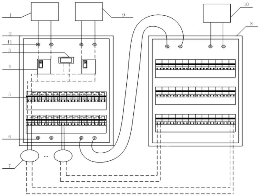
[0053] On the basis of Embodiment 1, a DC emergency transfer method, the connection relationship is as follows figure 2 shown, including steps:
[0054] S1: The upper terminal block 6 of the DC emergency transfer box 2 is connected to the DC power supply 1;
[0055] S11: the second upper terminal block 6 of the DC emergency transfer box 2 is connected to the inverter backup power supply 9;
[0056] S2: The lower terminal block 11 of the DC emergency transfer box 2 is connected to the old DC power distribution box 8 to eliminate the voltage difference between the two, and the old DC power distribution box 8 is connected to the system power supply 10;
[0057] S3: Select the air switch 5 of the corresponding capacity on the DC emergency transfer box 2 according to the power of the load 7, connect the load 7 through the air switch 5, and close the air switch 5. At this time, the load 7 is connected by the DC emergency transfer box 2 and the old DC power distribution box 8 supp...
Embodiment 3
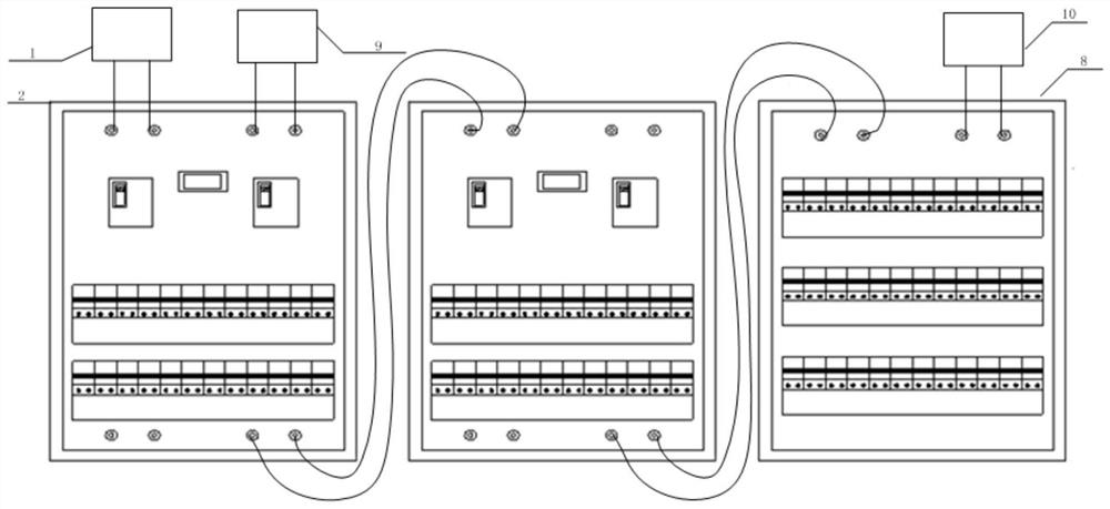
[0069] Such as image 3 As shown, in this embodiment, on the basis of Embodiment 2, a lower connection terminal row 11 of No. 1 DC emergency transfer box 2 is connected with an upper connection terminal row 6 of No. 2 DC emergency transfer box 2 to form a parallel transfer Connection box group; the lower terminal block 11 of the No. 2 DC emergency transfer box 2 is connected to the target DC power distribution box, and the two upper terminal blocks 6 of the No. 1 DC emergency transfer box 2 are respectively connected to the DC power source 1 and the inverter The backup power supply 9, the target DC power distribution box is connected to the system power supply 10, and the air switches 5 of the two emergency transfer boxes 2 can be used for the transfer of the load 7 at the same time. When the number of loads 7 in the target DC power distribution box is too large , the operation mode of this embodiment can be selected to ensure the safe operation of the direct current switching...
PUM
 Abstract
Description
Claims
Application Information
 - R&D Engineer
- R&D Manager
- IP Professional
- Industry Leading Data Capabilities
- Powerful AI technology
- Patent DNA Extraction
Browse by: Latest US Patents, China's latest patents, Technical Efficacy Thesaurus, Application Domain, Technology Topic, Popular Technical Reports.
© 2024 PatSnap. All rights reserved.Legal|Privacy policy|Modern Slavery Act Transparency Statement|Sitemap|About US| Contact US: help@patsnap.com


