Blade hoisting auxiliary structure for wind driven generator, system and hoisting method
A technology for wind turbines and auxiliary structures, which is applied in the assembly of wind turbines, transportation of wind turbines, and wind power generation, etc., can solve the problems of increasing the safety risk of on-site construction and increasing the difficulty of hoisting, so as to solve the difficulties of hoisting, reduce the difficulty, and reduce the The effect of labor
- Summary
- Abstract
- Description
- Claims
- Application Information
AI Technical Summary
Problems solved by technology
Method used
Image

Examples
Embodiment 1
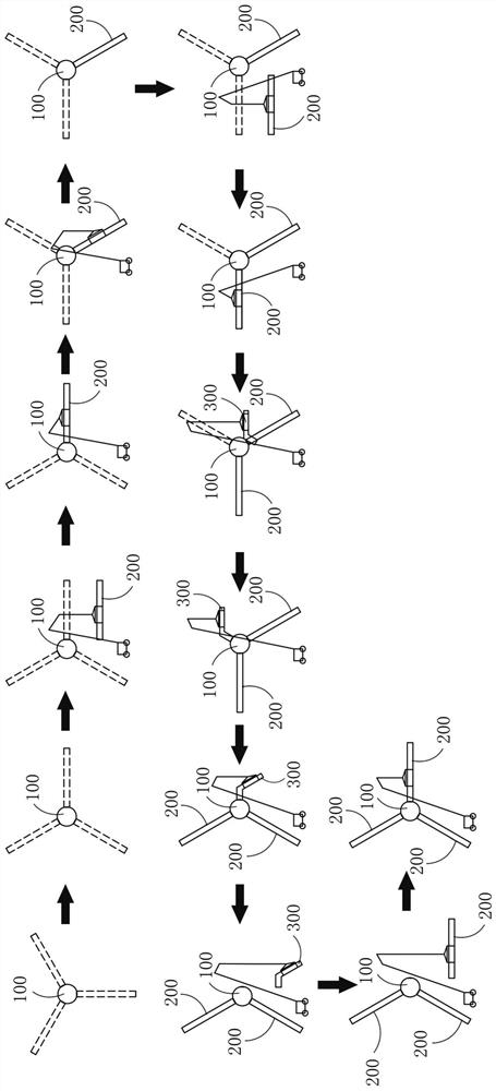
[0077] like image 3 As shown, the wheel hub 100 can be hoisted to the position of the nacelle and installed, at this time, a connecting flange of the wheel hub 100 can be located in a vertical position. Then, the wheel hub 100 can be rotated, for example but not limited to, the wheel hub 100 can be rotated 30° clockwise and then locked, and the rotation process can be performed by means of internal or external cranking. Afterwards, the blade 200 can be hoisted horizontally and inserted horizontally onto the connecting flange at the horizontal position. Then, the hub 100 is unlocked. At this time, due to the gravity of the installed blade 200, the hub 100 will rotate clockwise until the other connecting flange is in a horizontal position. For example, but not limited to, the hub 100 can be clockwise during this process. The direction is rotated by 60°, at this time, the hub 100 can be locked again, and the second blade 200 can be hoisted horizontally, so that the blade 200 ca...
Embodiment 2
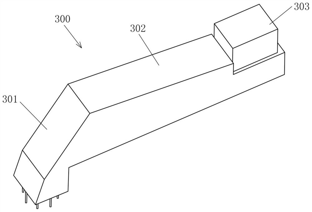
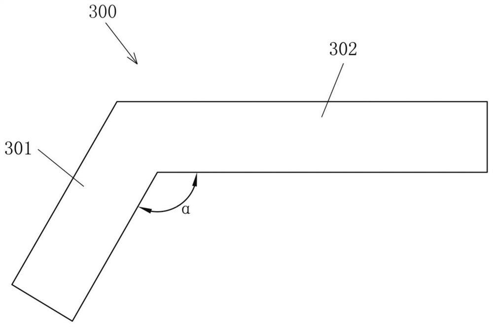
[0079] refer to Figure 4 , the difference between this embodiment and Embodiment 1 is that after the second blade 200 is fixed on the hub 100, the hub 100 can be unlocked first, and under the action of the torque of the two blades 200, the hub 100 will Rotate counterclockwise, for example but not limited to, rotate the hub 100 counterclockwise by 30°, the connecting flange in the vacant state will be in a vertical position, at this time the hub 100 can be locked for subsequent installation of the blade lifting auxiliary structure 300. Then, the blade lifting auxiliary structure 300 can be hoisted horizontally, the first included angle between the first beam 301 and the horizontal section 302 of the blade lifting auxiliary structure 300 can be 90°, and the blade lifting auxiliary structure 300 can be moved to a suitable position until the first The first end of a beam 301 is docked with the connecting flange in a vacant state. In this state, the blade lifting auxiliary structu...
Embodiment 3
[0082] refer to Figure 5 , the difference between this embodiment and Embodiment 1 is that after the second blade 200 is fixed on the hub 100, the hub 100 can be unlocked first, and under the action of the torque of the two blades 200, the hub 100 will Rotate counterclockwise, for example but not limited to, rotate the hub 100 counterclockwise by 15°, the connecting flange in the vacant state will be in the first position, and at this time the second included angle β can be 75°, and the hub 100 is locked at this time . Then, the blade lifting auxiliary structure 300 can be hoisted horizontally, the first included angle α between the first beam 301 and the horizontal section 302 of the blade lifting auxiliary structure 300 can be 105°, and the blade lifting auxiliary structure 300 can be moved to a suitable position until The first end of the first beam 301 is docked with the connecting flange in a vacant state, and the blade lifting auxiliary structure 300 can be fixed on th...
PUM
 Abstract
Description
Claims
Application Information
 - R&D
- Intellectual Property
- Life Sciences
- Materials
- Tech Scout
- Unparalleled Data Quality
- Higher Quality Content
- 60% Fewer Hallucinations
Browse by: Latest US Patents, China's latest patents, Technical Efficacy Thesaurus, Application Domain, Technology Topic, Popular Technical Reports.
© 2025 PatSnap. All rights reserved.Legal|Privacy policy|Modern Slavery Act Transparency Statement|Sitemap|About US| Contact US: help@patsnap.com